“Coating thickness shall be measured in accordance with SSPC: The Society for Protective Coatings Paint Application Standard No. 2 (SSPC-PA 2)” is a simple enough statement, yet this common specification requirement is often misinterpreted, or regarded as a document that simply states how to measure paint thickness, something we already profess to know how to do. Yet the requirements of SSPC-PA 2 regarding gage calibration, verification of gage accuracy and adjustment procedures, the number of measurements to obtain, and the tolerance of the measurements is complex and should be fully understood by the specification writer before invoking it in a contract.
On more than one occasion I have heard it asked, “When did SSPC-PA 2 and dry film thickness measurement become so complicated?” In fact, when you take a close look, the practice of measuring coating thickness isn’t that complex. We have allowed technology to make it more complex, yet easier. We can gather hundreds of gage readings in a relatively short period of time; batch the measurements; print the data or upload it to a computer for graphing; report the highest, the lowest, the mean and standard deviation of the collected data; incorporate digital images of the structure/coated area; and can even program the gage to produce an audible signal if a spot measurement is outside of the tolerable range. I am sure there are other “bells and whistles” that I am leaving out, but my point is that while we are able to do a lot with the readings that are obtained, the process of measuring coating thickness involves 4 or 5 very basic steps:
Step 1: Instrument Calibration
Step 2: Verification of Gage Accuracy on Certified Coated Standards or Certified Shims
Step 3: Base Metal Reading Acquisition or Gage Adjustment (using certified or measured shims)
Step 4: Measurement of Coating Thickness
Step 5: Correction for Base Metal Reading (if acquired).
Each of these five steps will be described in this article
Some History
SSPC-PA 2, was originally published as a temporary standard over 40 years ago in 1973 (73T) as “Measurement of Dry Coating Thickness with Magnetic Gages.” The standard referenced gages like the one shown in Figure 1, which are now all but obsolete. The standard has been updated on multiple occasions (2004, 2009, and 2012). The latest edition of the standard (“Procedure for Determining Conformance to Dry Coating Thickness Requirements”) was published on January 26, 2015.
In nearly the same timeframe, the 2005 version of ASTM D7091, “Standard Practice for Nondestructive Measurement of Dry Film Thickness of Nonmagnetic Coatings Applied to Ferrous Metals and Nonmagnetic, Nonconductive Coatings Applied to Non-Ferrous Metals” was also being revised and updated. It too was published in 2012, and was updated again in 2013. The most current version of the ASTM standard focuses on proper gage use, while SSPC-PA 2 focuses primarily on the frequency of measurements and the acceptability of the acquired measurements. All references to the frequency of measurements were removed from the ASTM standard. The two documents are designed to be used in conjunction with each another. It is also important to note that both documents address the measurement of coating thickness on both ferrous and non-ferrous metal substrates. Prior to 2012, SSPC-PA 2 only addressed measurement of coatings on steel.
Gage Types
SSPC-PA 2 addresses two types of dry film thickness gages, both of which are supplied by a variety of manufacturers. Magnetic pull-off gages are categorized as Type 1 (Figure 2). These gages were designed in the 1950’s and while their use has declined, they are still readily available and are still used by some. For these gages, a permanent magnet is brought into direct contact with the coated surface. The force necessary to pull the magnet from the surface is measured and converted to coating thickness, which is displayed on a scale on the gage. The operating principle is quite simple. Less force is required to remove the magnet from a thick coating, while more force is required to remove the magnet from a thinner one. The scale is not linear.
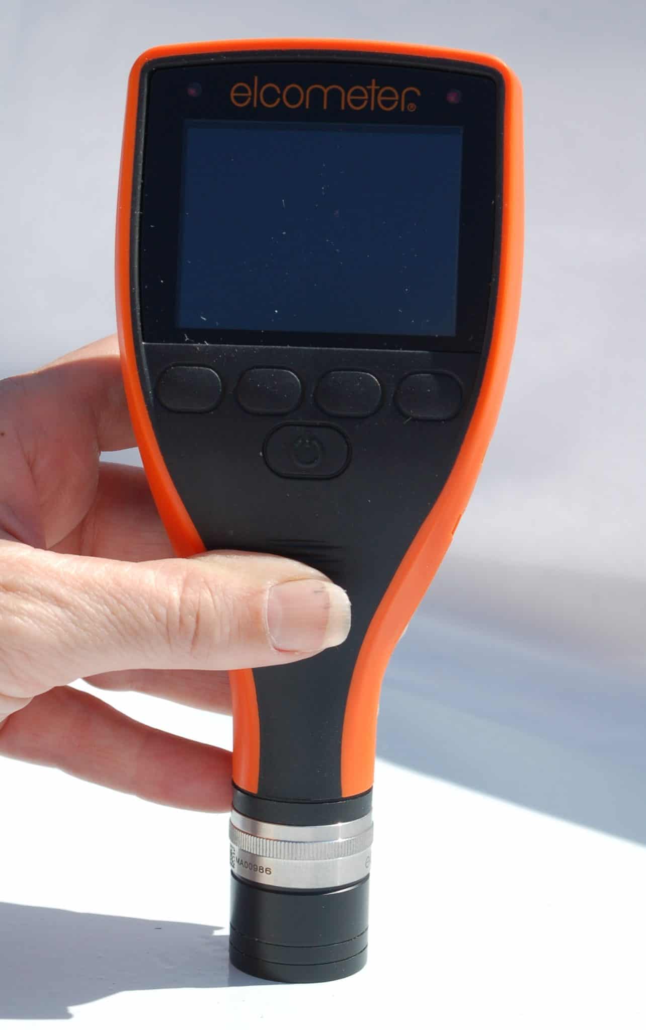
Electronic gages are categorized as Type 2 (Figure 3). These gages use electronic circuitry to convert a reference signal into coating thickness and are more popular that Type 1 gages. They are typically regarded to be faster, more accurate and easier to use.
Gage Calibration, Accuracy Verification and Adjustment
ASTM D 7091 describes three operational steps that must be performed prior to coating thickness measurement to help assure the reliability of the measurements. These steps include (1) gage calibration, (2) verification of gage accuracy and (3) gage adjustment. These steps are incorporated by reference in SSPC-PA 2 and are completed before obtaining coating thickness measurements to determine conformance to a specified coating thickness range. Stated more simply, you measure the thickness of something you know the thickness of, before you measure the thickness of something you don’t. Verification of gage accuracy is typically performed using certified coated thickness standards (for Type 1 or Type 2 gages) or certified shims (Type 2 gages). Adjustment of Type 2 gages to compensate for substrate characteristics (described later) is typically performed using certified shims. Measured shims (individually labeled with a stated thickness value) commonly supplied with Type 2 gages can also be used for gage adjustment.
Dry film thickness gages are calibrated by the equipment manufacturer, their authorized agent or an accredited calibration laboratory (under controlled conditions). A test certificate or other documentation showing traceability to a national metrology institution is required. While there is no standard time interval for re-calibration, an interval is usually established based upon experience and the work environment. A one-year calibration interval is a typical starting point suggested by gage manufacturers.
Verifying Gage Accuracy for SSPC- PA 2
To guard against measuring with an inaccurate gage, SSPC-PA 2 requires that gage accuracy be verified (at a minimum) at the beginning and end of each work shift according to the procedures described in ASTM D 7091. If a large number of measurements is being obtained, the user may opt to verify gage accuracy during measurement acquisition (e.g., hourly). If the gage is dropped or suspected of giving erroneous readings during the work shift, its accuracy should be rechecked.
Verifying the Accuracy of Type 1 Gages
The accuracy of Type 1 (magnetic pull-off) gages is verified by placing the gage probe onto a certified coated thickness standard (Figures 4 and 5). SSPC-PA 2 defines a Certified Standard as, “Coated or plated metal plates (containing an uncoated plate for zero reference) with assigned values traceable to a national metrology institution (such as NIST). Also, uncoated shims of flat plastic sheet with assigned values traceable to a national metrology institution.” A one-point or two point accuracy verification procedure can be performed; typically the two-point verification provides greater accuracy. If a one-point verification procedure is adopted, the coated standard should be selected based on the intended range of use. For example, if the intended use is between 4 and 6 mils, then a 5-mil coated standard is appropriate. Using the same example, if a two-point verification procedure is adopted, then a 2 -mil and an 8-mil set of coated standards (slightly below and above the intended range of use) is appropriate. Unless explicitly permitted by the gage manufacturer, shims (certified or measured) are not permitted for verification of accuracy of Type 1 gages.
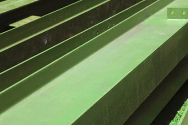
The final step in the process is to obtain a set of base metal readings (BMRs) to compensate for substrate characteristics including (but not limited to) substrate metallurgy, geometry, thickness/thinness and roughness (Figure 6). These readings represent themeasurement device. SSPC-PA 2 states that a minimum of 10 locations (arbitrarily spaced) should be measured (one reading per location), then averaged. This average base metal reading is then deducted from subsequent coating thickness measurements to remove any effect of the base metal surface and its conditions.
Since Type 1 gages cannot be adjusted by the user, it was believed that a “correction value” could be applied to the coating thickness readings to compensate for the inaccuracy of the gage. For example, if a gage reads 5.7 mils on a 5-mil coated standard, a 0.7-mil “correction value” could be deducted from subsequent coating thickness measurements. However, since Type 1 gages are non-linear, one cannot assume a linear correction value across the full range of the gage. While the gage may be out of tolerance by 0.7 mil at 5 mils, it may be out of tolerance by a greater or lesser amount at a different thickness. Accordingly, SSPC-PA 2 states that this practice is not appropriate since the gage scale in non-linear.
Verifying the Accuracy of Type 2 Gages
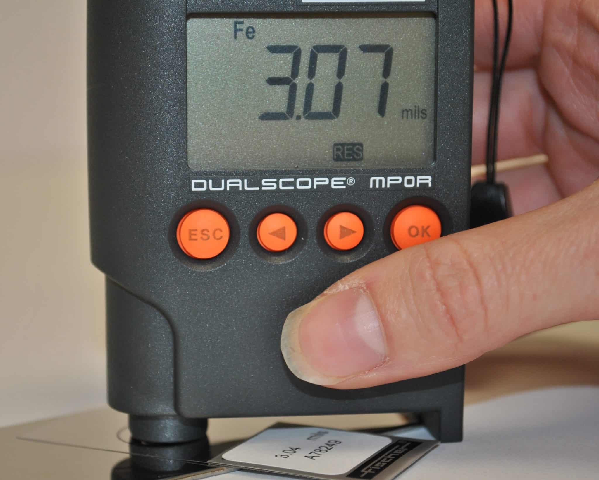
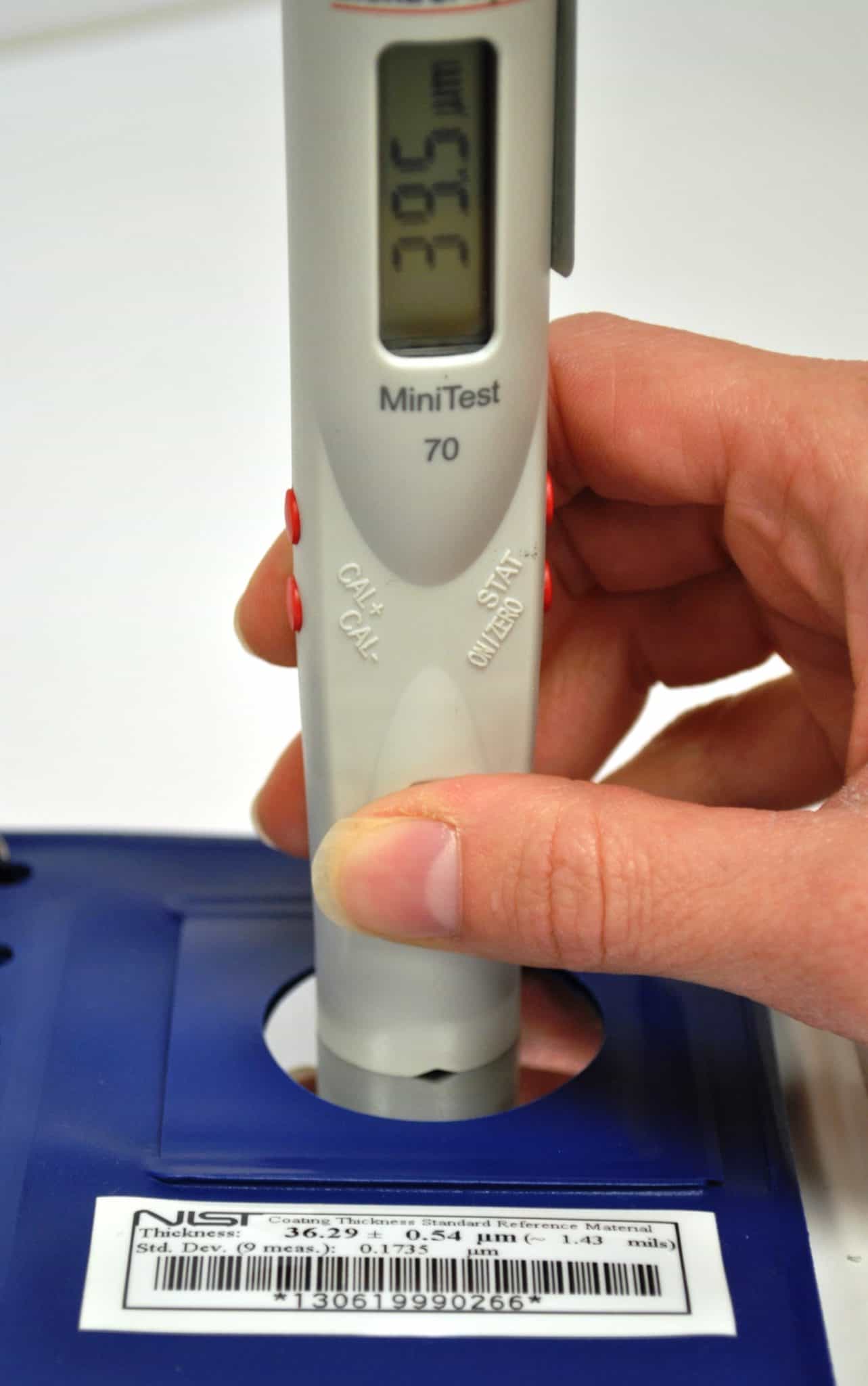
The accuracy of Type 2 (electronic) gages can be verified by placing the gage probe onto a certified coated thickness standard (described for Type 1 gages) or certified shims (Figures 7 and 8). The certified shim should be placed onto a smooth, uncoated metal surface to remove any effect of the surface roughness during this process. A one-point or two point accuracy verification procedure can be performed (as described for Type 1 gages).
Adjusting Type 2 Gages
The final step in the process is to adjust the gage on the surface to which the coating will be applied. This is accomplished by placing a certified or measured shim (or shims) onto the prepared, uncoated metal surface and adjusting the gage (when feasible) to compensate for substrate characteristics including (but not limited to) substrate metallurgy, geometry, thickness/thinness and roughness (Figure 9). The gage reading is adjusted to match the thickness of the shim, which effectively removes any influence from the underlying surface.
This step sounds reasonably straightforward but poses several “hidden” challenges. First, once the surface is coated (e.g., with a primer), an uncoated surface may no longer be available for subsequent gage adjustments, so the user may want to have a similar surface prepared and reserved for future gage adjustments on a given project. Naturally this surface must be representative of the metallurgy, geometry, thickness/thinness and roughness of the actual surface, which can be challenging to acquire. Secondly, some Type 2 gages cannot be adjusted. In this case, the user will need to obtain base metal readings (BMR) from the prepared, uncoated substrate (described earlier for Type 1 gages). While many Type 2 (electronic) gages have a “zero-set” function, the gages should never be adjusted to zero unless the surface is smooth.
Required Number of Coating Thickness
Measurements to Determine Conformance to a Specification
This section of SSPC-PA 2 is where many users get confused, which can result in either under or over-inspection. Arguably the most critical section in the document, Section 8 describes how many areas to check, the size of the areas, the number of measurements to obtain in each area and what steps to take if spot or area measurements do not conform to the specification.
SSPC-PA 2 contains three definitions that are critical to understanding this next area of discussion. They include:
Gage Reading: A single instrument reading.
Spot Measurement: The average of three, or at least three gage readings made within a 4 cm (~1.5 inch) diameter circle. Acquisition of more than three gage readings within a spot is permitted. Any unusually high or low gage readings that are not repeated consistently are discarded. The average of the acceptable gage readings is the spot measurement.
Area Measurement: The average of five spot measurements obtained over each 10 m2 (~100 ft2) of coated surface, or portion thereof.
An area is defined as approximately 100 square feet. Within each area, five randomly spaced spots are selected. Each spot consists of a 1 ½ inch diameter circle. A minimum of three gage readings are obtained in each spot, culminating in a minimum of fifteen gage readings within an area. Unusually high or low gage readings that cannot be repeated consistently are discarded. The average of the three acceptable gage readings is the spot measurement. Figure 10 is from Appendix 1 in SSPC-PA 2. It depicts an approximate 100 square foot area containing gage readings and spot measurements.
The number of areas that must be measured for coating thickness varies, depending on the size of the coated area. There are three categories of coated area: less than 300 square feet; 300-1,000 square feet; and greater than 1,000 square feet. For areas containing less than 300 square feet of coated surface, every 100 square foot area must be measured for coating thickness. For areas of coating 300 to 1,000 square feet, three random areas are selected and measured. For areas of coating exceeding 1,000 square feet, three random areas are selected from the first 1,000 square feet, plus one additional area for each additional 1,000 square feet.
Because areas of coating often exceed 1,000 square feet, our example will be based on this third tier (> 1,000 square feet). Let’s assume that the total coated area (perhaps the area coated during a work shift, although SSPC-PA 2 does not equate coated area with work shift) is 12,500 square feet. A total of 15 areas must be measured (3 in the first 1000 square feet and one additional area in each remaining 1000 square foot area or portion thereof; in this example 12). This culminates in a total of 75 spot measurements (15 x 5) and a minimum of 225 gage readings (15 x 5 x 3). If spot measurement variances result in area measurements that do not meet the specification, then additional spot measurements are acquired (radiating outward in eight directions from the non-conforming area) to determine the magnitude of the non-conforming thickness. This process is described later in this article.
Acceptability of Gage Readings, Spot Measurements and Area Measurements
While individual gage readings that are unusually high or low (and cannot be repeated consistently) can be discarded, there are limitations on the thickness values representing the spot measurements (the average of three gage readings). A minimum and a maximum thickness are normally specified for each layer of coating. However, if a single thickness value is specified and the coating manufacturer does not provide a recommended range of thickness, then the minimum and maximum thickness for each coating layer is established by SSPC-PA 2 at +/- 20% of the stated value. For example, if the specification requires 3 mils dry film thickness and the coating manufacturer does not provide any additional information regarding a recommended thickness range, then by default the specified range is established as 2.4-3.6 mils. Therefore, it is important for the specifier to indicate an acceptable range for each coating layer, as the coating may not perform at the lower thickness. To assist the specifier, the 2012 edition of SSPC-PA 2 incorporates a Restriction Level Table (Figure 11). This enables the specifier to select from five different restriction levels related to spot and area measurements.
Figure 11 (Table 1)
Coating Thickness Restriction Levels
|
Thickness |
Gage Reading |
Spot Measurement |
Area Measurement |
| Level 1 | |||
| Minimum | Unrestricted | As specified | As specified |
| Maximum | Unrestricted | As specified | As specified |
| Level 2 | |||
| Minimum | Unrestricted | As specified | As specified |
| Maximum | Unrestricted | 120% of maximum | As specified |
| Level 3 (Default) | |||
| Minimum | Unrestricted | 80% of minimum | As specified |
| Maximum | Unrestricted | 120% of maximum | As specified |
| Level 4 | |||
| Minimum | Unrestricted | 80% of minimum | As specified |
| Maximum | Unrestricted | 150% of maximum | As specified |
| Level 5 | |||
| Minimum | Unrestricted | 80% of minimum | As specified |
| Maximum | Unrestricted | Unrestricted | Unrestricted |
Level 1 is the most restrictive and does not allow for any deviation of spot or area measurements from the specified minimum and maximum thickness, while Level 5 is the least restrictive. Depending on the coating type and the prevailing service environment, the specifier can select the dry film thickness restriction level for a given project. The specifier may also invoke a maximum thickness threshold for Level 5 Spot or Area measurements for a generic product type and/or service environments that will not tolerate an unlimited thickness. If no Restriction Level is specified then Level 3 is the default, which is based on the 2004 and 2009 versions of SSPC-PA 2 (what many users have become accustomed to).
For the purpose of final acceptance of the total dry film thickness, the cumulative thickness of all coating layers in each area must be no less than the cumulative minimum specified thickness and no greater than the cumulative maximum specified thickness.
For example, assume that the specification requires a 4 to 6 mil application of primer. The actual minimum and maximum spot and area thickness requirements are shown in Figure 12 for each of the five restriction levels.
Figure 12 (based on a 4-6 mil requirement)
|
Thickness |
Gage Reading |
Spot Measurement |
Area Measurement |
| Level 1 | |||
| Minimum | Unrestricted | 4 mils | 4 mils |
| Maximum | Unrestricted | 6 mils | 6 mils |
| Level 2 | |||
| Minimum | Unrestricted | 4 mils | 4 mils |
| Maximum | Unrestricted | 7.2 mils | 6 mils |
| Level 3 (Default) | |||
| Minimum | Unrestricted | 3.2 mils | 4 mils |
| Maximum | Unrestricted | 7.2 mils | 6 mils |
| Level 4 | |||
| Minimum | Unrestricted | 3.2 mils | 4 mils |
| Maximum | Unrestricted | 9 mils | 6 mils |
| Level 5 | |||
| Minimum | Unrestricted | 3.2 mils | 4 mils |
| Maximum | Unrestricted | Unrestricted | Unrestricted |
Determining the Magnitude of Non-conforming Thickness
If a non-conforming area is identified, spot measurements are made at 5-foot intervals in eight equally spaced directions radiating outward from the nonconforming area as shown in Figure 13 below.
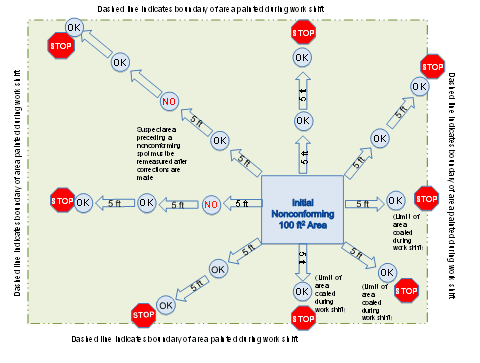
If there is no place to measure in a given direction, then no measurement in that direction is necessary. Spot measurements are obtained in each direction (up to the maximum surface area coated during the work shift) until two consecutive conforming spot measurements are acquired in that direction, or until no additional measurements can be made. Acceptable spot measurements are defined by the minimum and maximum values in the contract documents. That is, no allowance is made for variant spot measurements (e.g., +/- 20%), which is consistent with the practice followed when determining the area DFT.
On complex structures or in other cases where making spot measurements at 5-foot intervals is not practical, spot measurements are taken on repeating structural units or elements of structural units. This method is used when the largest dimension of the unit is less than 10 feet. Spot measurements are obtained on repeating structural units or elements of structural units until two consecutive units in each direction are conforming or until there are no more units to test.
Non-compliant areas are demarcated using removable chalk or another specified marking material and documented. All of the area within five feet of any non-compliant spot measurement is considered non-compliant. For a given measurement direction or unit measurement, any compliant area or unit preceding a non-compliant area or unit is designated as suspect, and as such is subject to re-inspection after corrective measures are performed.
Reporting
Section 10, Reporting was added to the standard in 2015. This section lists the items to report when documenting dry film thickness data, including: the type of instrument used, including the name of the manufacturer, the model number, the serial number and the date of calibration; the type of Certified Standard used to verify gage accuracy including the manufacturer, the model number, the serial number and the thickness value(s); the thickness of the measured shim(s) used to adjust a Type 2 gage (if used); the average Base Metal Reading (if applicable); the Spot and Area Measurements; and the gage operator and the date the readings were obtained. Depending upon the application, the individual gage readings may also be recorded.
Appendices
There are nine appendices in the 2015 version of SSPC-PA 2. Three appendices were added within the past 3 years or so (two were added in 2012 and one was added in 2015; the remaining were in the 2004 edition). The newer appendices are highlighted below. The appendices to SSPC-PA 2 are non-mandatory but may be invoked by contract documents.
Appendix 6: Method for Measuring the Dry Film Thickness of Coatings on Edges
For decades, the industry was cautioned about taking coating thickness measurements within 1 inch of an edge, let alone on an edge. However, several Type 2 (electronic) gage manufacturers offer a variety of probe configurations, some of which are less affected by proximity to edges and are designed to better measure the thickness of coatings on edges (Figure 14). Obviously the gage operator should consult the manufacturer’s instructions before measuring coating thickness on edges.
Prior to measurement of coating thickness on edges, the gage and probe should be verified for accuracy by placing a thin, flexible shim (certified or measured) onto the prepared, uncoated edge. Adjustments to the gage may or may not be required. This procedure also verifies that the probe configuration will accommodate the edge configuration prior to coating thickness data acquisition.
Once verification of accuracy and adjustments are made, a minimum of three gage readings are taken within 1.5 linear inches of coated edge. The average of the gage readings is considered a spot measurement. The number of spot measurements along the edge will vary depending on the total length of the coated edge.
Appendix 7: Method for Measuring Dry Film Thickness on Coated Steel Pipe Exterior
Appendix 7 was added to accommodate pipe coaters that need to determine coating thickness conformance on non-flat (or non-plate) areas, including smaller pipe sections on a cart or rack and longer pipe spools.


Pipe sections that are loaded onto a cart or rack can be considered a complete unit (Figure 15). The total number of spot and area measurements is based on the total square footage of pipe on the cart or rack. The square footage is calculated as:
Area = (length of each pipe x circumference) x number of pipe sections on cart or rack
Circumference = pi x diameter
Example: 10 pieces of 48” long x 9” diameter pipe on a cart or rack
4’ x (3.14 x 0.75’) = 9.4 sq. feet per pipe section.
9.4 sq. feet per pipe section x 10 pipe sections = 94 sq. ft.
Since the total area is less than 100 sq. ft., 5 spots are measured (each spot is a minimum of 3 gage readings).
Some carts may have several small pipe sections, wherein the total coated surface may exceed 100 square feet. In this case, a Pipe DFT Frequency Factor shown below may be invoked.
- Pipe DFT Frequency Factor 2 = (length of each pipe x circumference) x no. of pipe sections on cart or rack = (number of spot measurements) x 2
- Pipe DFT Frequency Factor 3 = (length of each pipe x circumference) x no. of pipe sections on cart or rack = (number of spot measurements) x 3
- Pipe DFT Frequency Factor 4 = (length of each pipe x circumference) x no. of pipe sections on cart or rack = (number of spot measurements) x 4
- Pipe DFT Frequency Factor 5 = (length of each pipe x circumference) x no. of pipe sections on cart or rack = (number of spot measurements) x 5
- Pipe DFT Frequency Factor 6 = (length of each pipe x circumference) x no. of pipe sections on cart or rack = (number of spot measurements) x 6
Based on the example above, if “Pipe DFT Frequency Factor 4” was invoked, 20 spot measurements would be taken (5 spots x 4x Frequency Factor)
Pipe spools that are not loaded onto a rack or cart are typically measured individually (Figure 16). The number and locations of spot measurements are based on Table A7 (Figure 17). Three sets of four circumferential spot measurements should be obtained on pipe spools less than 10 feet in length.
Figure 17 (Table A7)
Number and Locations of Spot Measurements – Pipe Spools
|
Pipe Diameter |
Circumferential Spot Measurements |
Interval Spacing |
| Up to 12” | 4 evenly spaced | 10 feet apart |
| 14” – 24” | 6 evenly spaced | 10 feet apart |
| >24” | 8 evenly spaced | 10 feet apart |
Appendix 9 (added in 2015): Precaution Regarding Use of the Standard for Coating Failure Investigations
Appendix 9 was added as a cautionary statement, as coating thickness data collected during a coating failure investigation are not typically acquired in spots or areas, but rather in failing and non-failing areas, based on observed patterns of failure, etc. Obtaining coating thickness measurements according to the frequency described in SSPC-PA 2 across the entire structure may be of little value during a coating failure investigation and can be cost prohibitive. ASTM D7091 is the more appropriate reference for this particular application, as measurement frequency is not addressed in the standard.
Conclusion
SSPC-PA 2 has undergone significant changes in an attempt to make the standard more complete, in concert with ASTM D7091, easier to perform in the shop and field, and to provide the specifier with options for coating thickness restrictions based on the type of structure, the coatings to be applied and the service environment.
Change is never easy… communicating the new requirements of this standard to the industry is challenging, but essential. One conduit is through training and education. For example, SSPC offers a short course, “Using SSPC-PA 2 Effectively” that has been updated to reflect changes made to the standard. Free webinars are available through JPCL/Paintsquare for those that cannot participate in instructor-led training. Updates to SSPC and other industry-provided inspector training and certification courses (and the associated instructor education) will be critical to fully understanding and effectively communicating the requirements of this highly regarded industry standard.
Summary of Changes (2012 to 2015)
SSPC Paint Application Standard No. 2 (SSPC-PA 2), “Procedure for Determining Conformance to Dry Coating Thickness Requirements” was updated from the May 2012 version and was published on January 26, 2015. The information presented in the graphics below illustrates the shortcomings of the 2012 version of the standard and the major updates to the 2015 version of the standard that address these shortcomings. Items 1-7 in the “shortcomings” figure (Figure 1) correspond directly to Items 1-7 in the “Improvements” figure (Figure 2).
Figure 1: Shortcomings of SSPC-PA 2 (May 1, 2012 Version)
- Scope disallowed the use of the Measurement Frequency for Measuring Coating Thickness during a Coating Failure Investigation
- No Definition of Certified Standards
- No Specific Information Regarding Verification of Accuracy and Adjustment
- Accuracy Verification of Type 1 Gages was performed using “Smooth Test Blocks” Only (no allowance for shims/foils)
- Diagram Illustrating the Procedure for Determining Magnitude of Non-conforming Area Needed Improvement
- No “Reporting” Section
- Appendix 7 (Measurement on Pipe Surfaces) Required Clarification
Figure 2: Improvements to SSPC-PA 2 (January 26, 2015 version)
1. Statement was removed from the Scope. Appendix 9 (non-mandatory) was created: “Precaution Regarding Use of the Standard for Coating Failure Investigations.”
2. Certified Standards Definition Added. “Coated or plated metal plates (containing an uncoated plate for zero reference) with assigned values traceable to a national metrology institution. Also, uncoated shims of flat plastic sheet with assigned values traceable to a national metrology institution.”
3. Information Regarding Verification of Accuracy and Adjustment added. “Verification of accuracy shall be performed using certified standards. Type 2 gage adjustments to compensate for characteristics including (but not limited to) substrate metallurgy, geometry, thickness/thinness and roughness shall be performed using certified shims. The measured shims commonly supplied with Type 2 gages are also acceptable for gage adjustment.”
Note: Step 1: Verification of Accuracy using Certified Standards
Step 2: Adjustment to correct for roughness via BMR or shims (certified or measured shims)
4. Certified Shims are permitted to be used with Type 1 Gages if Explicitly Approved by the Gage Manufacturer
5. Detailed Illustration Added to Appendix A (Figure A1.2)
6. Reporting Section Added (Section 10)
7. Examples of Square footage Calculations for Pipe and Pipe DFT Frequency Factor Calculations Added to Appendix 7
About the Author:
 William D. Corbett is the Vice President and Professional Services Group Manager for KTA-Tator, Inc. He holds an A.D. in Business Administration from Robert Morris University and has been employed by KTA for over 33 years. Mr. Corbett is an SSPC Certified Protective Coatings Specialist, an SSPC Level 3 Certified Protective Coatings Inspector, an SSPC Level 2 Certified Bridge Coatings Inspector and a NACE International Level 3 Certified Coatings Inspector. He was the co-recipient of the SSPC 1992 Outstanding Publication Award, co-recipient of the 2001 JPCL Editor’s Award, received SSPC’s Coatings Education Award in 2006, and the SSPC 2011 John D. Keane Award of Merit. He is the author of the first, second and third editions of the KTA publication, Using Coatings Inspection Instruments. He also authored Chapter 8 of the SSPC Inspection of Coatings and Linings Handbook and co-authored Chapter 6, “Inspection” of the Steel Structures Painting Manual, Volume 1, Good Painting Practice. Mr. Corbett is a member of the ASTM International and SSPC: The Society for Protective Coatings, where he is Chair of the Education Committee and the Dry Film Thickness Committee
An excellent and useful article. Well done.
One of the issues that needs to be explained and discussed is using Test-Tex paper for measuring profile. Too many folks simply think if they can get a 2.5 mil or what ever the spec calls for and they are good. The number of peaks and valleys is also important. Are there any industry standards that address peak count versus simple profile that may only indicate a few peaks at that height.
Thanks,
Richard
Research conducted several years ago by Hugh Roper, Ray Weaver and Joe Brandon (published in the June 2005 issue of the Journal of Protective Coatings & Linings) demonstrated improved coating adhesion properties and greater resistance to corrosion undercutting (of a damaged coating) with higher peak count/greater peak density. This research culminated in the development of ASTM D7127, “Standard Test Method for Measurement of Surface Roughness of Abrasive Blast Cleaned Metal Surfaces Using a Portable Stylus Instrument,” which includes peak count (Pc) as one of the measured parameters. This standard was published over 10 years ago in 2005. More recently (within the past year or so), Testex developed a new replica tape, which when inserted into the DeFelsko PosiTector Replica Tape Reader (RTR-P) produces 3-D color image of peak density and displays peak height as well as peak density (Pd, peaks per inch2).
It is important to recognize however that simply because all of this has been researched and the technology is in place to measure (quantify) it, does not make it contractually binding. If it is deemed important to a facility owner, it is up to a specifier to include this requirement in coating specifications that they prepare, as well as establish a minimum peak count/peak density, together with a minimum and maximum peak height (what we have come to know as surface profile). This too can create a potential conundrum – determining the correct abrasive mix that will generate the correct combination of height and density. You can produce one without the other.
SSPC-PA 17, “Procedure for Determining Conformance to Steel Profile/Surface Roughness/Peak Count Requirements” provides a method for determining whether the profile of a steel surface is in conformance with project specifications when using the instruments and procedures contained in ASTM D 4417 and D 7127. Requirements for frequency and location of instrument readings and evaluation criteria to ensure that the profile over the entire prepared surface complies with project requirements are included in the Standard. This standard was published in 2012 and will require updating to reflect current technology.
Finally, recent discussions within ASTM Subcommittee D01.46 (Industrial Protective Coatings) have been initiated to consider combining the procedures described in ASTM D7127 into ASTM D4417, then discontinue ASTM D7127 so that two standards on measurement of surface profile do not have to be maintained. Perhaps then peak count/density will get more attention from specification writers.
Bill Corbett
Very well done… information & examples are oftentimes little known outside the Coating mfgrs. Lab & community.
Very normative information in your article, thank you.