There are many challenges associated with cleaning and painting commercial buildings. Questions often arise regarding surface preparation, application and final thickness or appearance. Three of the many questions our consultancy group has encountered during the cleaning and painting of buildings are addressed in this article. The questions should be familiar situations to those in the field. However, sometimes a seemingly simple question can’t be resolved with a single answer.
As Seen in Durability & Design, Spring 2017 Issue

The questions include addressing lifting edges after a new coating is applied — and recognizing that lifting may be a sign that there is a deeper issue at play; understanding the roles the substrate, application method and coating thickness play in coverage rates; and options for measuring the dry film thickness of an existing coating on cementitious substrates and drywall.
QUESTION 1:
Lifting Edges, Likely Clues
The specification requires pressure washing the walls of a building to remove loose paint. Washing is being accomplished using a pressure of 3,000 psi with a fan tip. It is removing about 20 percent of the paint. When the new coating is applied, edges of the old paint are lifting. What is the best way to address the lifting?
Although the question is related to the treatment of localized lifting edges, the background information provided raises several additional concerns regarding the job itself.
But first, to answer the basic question: The areas of lifting should be removed by scraping, and the new coating reapplied and worked into the edges by brush or roller. When the next coat is applied, the surface should again be examined for lifting and the process repeated as necessary to seal the edges.
While these steps will address the lifting, the job description raises other questions with the project. The lifting indicates that the perimeter of the existing paint around the patches of removed coating are weak and unable to support the stresses imparted to the film as the newly applied material dries.
This could be due to inadequate cleaning and scraping to remove the loose coating before painting began. If this is the cause, the process described earlier is fine and the initial cleaning needs to be improved, but there may be more serious problems on this project.
The cleaning is being accomplished at a relatively low pressure and with a fan tip. This combination of pressure and tip is not very aggressive, and yet 20 percent of the paint is being removed. While it is likely that some peeling was visible before the work began, it can be assumed that the current cleaning process is responsible for the removal of much of the paint.
Twenty percent is a lot, and if it is scattered across one or more walls (rather than being concentrated in a single, well-defined area), it raises questions regarding the integrity and adhesion of the 80 percent of the coating that remains. The lifting edges may actually be an indication that the paint on the entire wall is too weak to be overcoated. If the integrity of the existing paint is poor, it can lead to widespread peeling and blistering of the newly applied coating.
There are a few things that can be done to investigate the situation, but the owner and/or specifier should be consulted first.
One suggestion is to pressure wash at 5,000 psi with a rotating tip. This will do a better job of detecting and removing weak paint, as it is much more aggressive than 3,000 psi with a fan tip, but care must be taken to avoid damaging the substrate (which is perhaps why the specification required the lower pressure and fan tip).

When performing washing at any pressure, it is important to control the distance between the end of the tip and the substrate. If held too close, good coating can be destroyed or the substrate damaged. If held too far away, poorly adhered coating may escape detection and removal. The difference between the two outcomes may only be a few inches, so it is best to discuss the optimum process with the equipment supplier based on the project-specific conditions and expectations, and do a few test areas.
If a lot more coating is removed by changing pressures or distances, the existing paint may not be of sufficient integrity to support the curing stresses and weight imparted by an overcoat.
Another suggestion is to conduct knife adhesion tests. A suitable test in this case is ASTM D6677, Evaluating Adhesion by Knife. Although it is best for a person experienced with coatings to do the testing and analysis, a layman can at least gauge the comparative adhesion around the building.
Testing locations should include the coating surrounding the patches where the old coating had been removed. Those results can be used as a baseline for comparing other areas. If the adhesion of the existing coating in other areas is similar to the adhesion surrounding failures, it should raise some concerns with overcoating the existing paint.
It would also be beneficial to test areas that have already been cleaned in addition to areas not yet touched. Areas exposed to sunlight and weathering can also be compared with areas that are protected from weathering exposure. Mapping this data can help to establish trends regarding the adhesion of the existing coating.
If the results suggest that the coating is too weak to be overcoated, it is best to know that before the entire building is painted, as there is a very real risk that widespread detachment of the coating a year down the road could occur. The lifting of the edges of old paint in this case may be a blessing in disguise.
QUESTION 2.
Troubleshooting Coverage
The coverage rate of the coating being applied to the building doesn’t match the coverage rate listed in the Product Data Sheet. How can this be investigated and resolved?
Coverage rates on Product Data Sheets (PDS) are theoretical and are heavily influenced by a number of factors, including the nature and condition of the substrate that is being coated.
For example, a new coating applied to a smooth substrate that is already covered with an intact coating will have very high coverage rates, while the same coating applied to bare split-faced concrete masonry unit (CMU) will exhibit much lower coverage rates. A porous substrate can require the application of a fair amount of coating to penetrate and seal the surface before a measurable film is created, effectively reducing the apparent overall coverage rate.
The Product Data Sheet shows the coverage rate, wet and dry film thickness, and solids by volume of the material:

The transfer efficiency of the application method is another factor to consider. When spraying, not all the material reaches the surface, as some is lost due to overspray and dryspray. The transfer efficiency by spray application will be lower than by brush and roller. It can also be lower when using conventional spray as opposed to airless. Transfer efficiency directly impacts the coverage rate achieved.
Coverage rates are also based on the application of a certain coating thickness. Obviously, when the applied coating is heavier than the thickness shown in the PDS, the coverage rate will be reduced.
The thickness of the coating can be checked quickly and easily during application using a wet film thickness gage. The PDS will typically indicate the wet film thickness that should be applied, but if it does not, the target wet film can be determined by plugging the desired dry film thickness and the percent solids by volume (both found in the PDS, as shown at left) into the following formula:
Wet Film Thickness = Dry Film Thickness ÷ % Solids by Volume of the coating material
For example, if the desired dry film thickness is 1.5 mils and the solids by volume is 40 percent, the target wet film thickness will be 3.75 mils, calculated as follows:
Wet Film Thickness = 1.5 mils ÷ 0.40 = 3.75 mils
To obtain valid wet film thickness readings, the examined surface must be relatively smooth; otherwise there will be irregular (inaccurate) wetting of the teeth of the gage. Because of this, in the case of CMU, it may be necessary to take readings on smooth mortar joints rather than on the block face itself.
If the coverage rates are still in question, a simple test can be conducted to determine if the coating is drying to the proper thickness. Apply the coating to a smooth uncoated steel substrate, but leave a small area bare. Measure the wet film thickness in specific areas at the time of application. Once the coating dries, use shims on the bare portion of the steel to make certain the instrument is accurately measuring the thickness over the given substrate. Go to the specific locations where the wet film readings were taken and measure the dry film thickness. If the dry film thickness measurement is correct for the wet film that was applied, the problems with coverage are unrelated to the paint material itself.
However, if it still appears that the paint is not drying to the expected thickness, you might consider pursuing a conclusive examination of the paint material by sending wet samples to a laboratory to determine the solids by volume of the material.
When sending samples, it is best to provide an unopened container to avoid the possibility of solvents having escaped during previous use, or the solids content of the remaining coating having been altered due to incomplete mixing when some of the material was removed during previous use. If a large, new container is opened to remove a sample for testing, it is critical that the coating be thoroughly mixed prior to transferring it to a small container, and that the smaller container is immediately and thoroughly sealed.
If the coverage rates are not meeting expectations, it is commonly due to factors other than the paint material itself. But, as indicated above, the paint can be easily examined in the field to determine if it is drying to the correct thickness or, if more analytical results are needed, through laboratory testing.
QUESTION 3.
Evaluating Coating Thickness
When there are questions regarding the thickness of a coating already applied to substrates such as masonry and drywall, how do you measure it?
The dry film thickness of coatings can be measured destructively or non-destructively. Destructive measurements include an in-situ microscopic technique or the removal of samples for field or laboratory measurement with a micrometer or microscope. Non-destructive measurements involve the use of specially designed ultrasonic thickness gages.
A common instrument used for determining coating thickness destructively is the Tooke Gage, which is used in accordance with ASTM D4138, Standard Practices for Measurement of Dry Film Thickness of Protective Coating Systems by Destructive, Cross Sectioning Means.
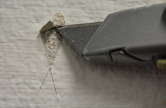
While the Tooke Gage is considered a destructive test, it is important to recognize that the “destruction” is only a small incision through the coating about the width of a pencil line and approximately 1 inch in length, which is easily touched up. The Tooke Gage is suitable for measurements of coating thickness up to 50 mils. In addition to determining total thickness, the Tooke Gage allows for the measurement of the thickness of each coat in multi-coat systems, provided there is a contrast in color between the coats.
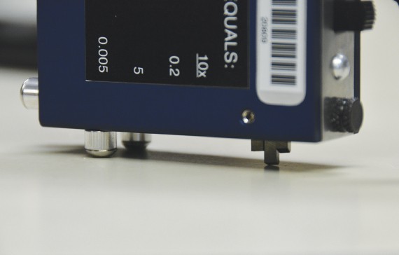
The instrument consists of a 50X microscope and special cutting tips for making incisions through the coating at known angles. Microscopic measurements of the width of the incisions are converted to depth or thickness. Three different cutting tips are supplied with the instrument, each one cutting through the film at a different angle. Tip selection is based on the thickness of the coating being measured.
There is three-point contact when making the incisions (two legs and a cutting tip). The legs and cutting tip are configured to make certain that the incisions are made perpendicular to the surface, which is critical to assuring the incision angles are precise. If the cutting angle was to vary, the measurements would be inaccurate. Because of this, any readings taken on rough surfaces can be suspect, even including readings on smooth face block.
One way to minimize errors on smooth face block is to place a thin rigid material on the surface (e.g., rigid plastic) to keep the legs of the instrument on the same plane when making the incisions. This can help prevent the gage from rocking during cutting, which can unintentionally change the cutting angle.
Another approach is to conduct the tests in the mortar joints, if wide enough, where the surface is smooth.
When used on wallboard, very light pressure should be used when making the incisions to avoid tearing the paper erratically, and therefore voiding the reading. If that doesn’t work, the tests can be conducted at a joint.
Another destructive approach involves removing chips of the dry coating for measurement. If the coating can be removed cleanly from the substrate, a micrometer can be used to measure the thickness. However, it is unlikely this will be feasible because remnants of the substrate will be attached to the backside of the coating sample, or portions of the coating will remain on the surface.
In either case thickness measurements using a micrometer will be incorrect. However, a sample with remnants of the substrate attached can be measured microscopically. This can be done in the field by collecting a sample with the substrate attached, then snapping it in half to create a reasonably smooth cross-section. The sample can then be examined edgewise using the microscope of the Tooke Gage. The sample can also be sent to the laboratory for more controlled sample preparation techniques and microscopic measurements.
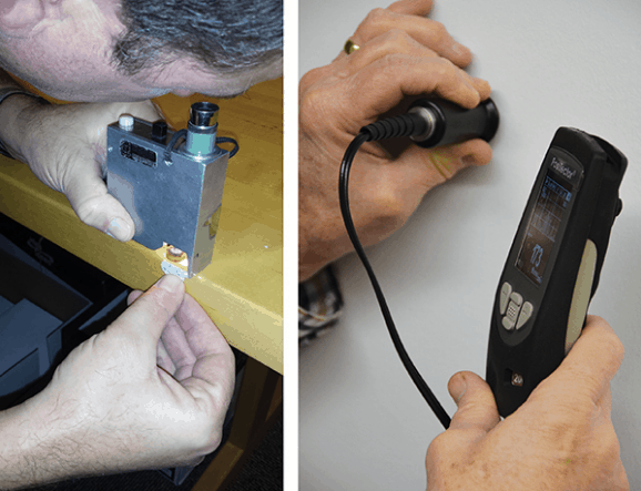
The thickness can also be measured non-destructively in the field using instruments that utilize ultrasound principles. This method is addressed in ASTM D 6132, Standard Test Method for Nondestructive Measurement of Dry Film Thickness of Applied Organic Coatings Using an Ultrasonic Gage.
A drop of couplant is applied to the surface of the coating to carry the ultrasound signal from the probe to the coated surface. Two readings are taken through the couplant, and the couplant is removed before going to the next location. At the new location, couplant is applied to the surface and the process is repeated. This instrument can be used on both painted concrete and drywall, but the surface must be reasonably flat in the locations where the readings will be taken. For example, it will not be possible to measure the thickness of the coating applied to split-faced block.
As is evident, there are both destructive and non-destructive methods for determining the thickness of the coating. Additionally, as discussed in the second question’s response, it is beneficial to measure the wet film thickness during application to better assure that the specified dry film thickness will be achieved.
 ABOUT THE AUTHOR: Kenneth A. Trimber, president of KTA-Tator Inc. has more than 40 years of experience in the industrial painting field. A NACE-Certified Coatings Inspector and SSPC Protective Coatings Specialist, he holds a bachelor’s degree from Indiana University of Pennsylvania. A past president of SSPC, Trimber is chairman of the association’s Commercial Coatings Committee, Surface Preparation Committee, and Containment Task Group, as well as a member of the Standards Review Committee. He is a past chairman of ASTM D1 on Paints and Related Coatings, Materials, and Applications and author of The Industrial Lead Paint Removal