
KTA’s Certified Coating Inspector Forum Volume 2, Issue No. 11 – November 2023focused on performing low and high voltage holiday detection, the steps that should be performed prior to testing including calibration and field verification, and the importance of calculating and selecting the proper test voltage when using a high voltage detector.
William Corbett, COO
AMPP Senior Certified Coating Inspector & Certified Protective Coating Specialist
KTA’s Certified Coating Inspector Forum is designed to provide professional development/continuing education on standards, inspection practices, new instruments, and other topics to help keep certified AMPP and FROSIO coating inspectors current. It represents the views of the author and KTA-Tator, Inc. It may or may not represent the views of AMPP: The Association for Materials Protection & Performance, even though SSPC, NACE, and AMPP standards are frequently referenced in the content.
Introduction
Perhaps one of the most important responsibilities of a certified coating inspector is staying abreast of advances in coating technology, new instrumentation, new industry standards, and changes to existing standards. When posted, notifications and updates in trade publications like the Journal of Protective Coatings & Linings (JPCL), Materials Performance (MP), and CoatingsPro Magazine (and their online counterparts) are helpful but aren’t always timely. One of the reasons we started publishing the Certified Coating Inspector Forum on the KTA University website is to help keep inspectors current with the technology, instruments, and standards that have a direct impact on what we do. This edition of the Certified Coating Inspector Forum is a perfect example of that. In this column we’ll be discussing changes to some very prominent standards for detection of holidays and pinholes in coating and lining systems. While holiday detection can sometimes be performed on coatings applied to concrete, the focus of this article is the detection of holidays on coatings applied to metallic substrates.
Industry Standards
There are four industry standards that address holiday detection on metallic substrates that may be invoked by project specifications, including:
- ASTM D5162, Standard Practice for Discontinuity (Holiday) Testing of Nonconductive Protective Coating on Metallic Substrates
- NACE SP0188, Discontinuity (Holiday) Testing of New Protective Coatings on Conductive Substrates
- ASTM G62, Standard Test Methods for Holiday Detection of Coatings used to Protect Pipelines
- ISO 29601, Corrosion Protection by Protective Paint Systems – Assessment of Porosity in a Dry Film
ASTM D4787, Standard Practice for Continuity Verification of Liquid or Sheet Linings Applied to Concrete Substrates may be specified when applying a lining to a concrete substrate but is not discussed in this article.
The four standards for metallic substrates are similar but there are differences, so it is important to reference the standard that is invoked by your project specification.
The 4 W’s of Holiday/Pinhole Detection: What, When, Where, and Why
Since it may have been a while since you were trained/certified, I thought we could all benefit from a quick refresher on the four W’s of Holiday/Pinhole Detection, including What, When, Where, and Why.
What is Holiday/Pinhole Detection: Holiday or pinhole detection is an inspection technique that is used to locate small voids (pinholes) or skips/misses (holidays) in an applied coating or lining system that may not be visible to the unaided eye. It may also be called discontinuity testing or jeeping (pipeline industry). To test for holidays and pinholes, the coating must be insulative (non-conductive) and the substrate must be conductive. There are two general categories of holiday/pinhole detection: Low Voltage (wet sponge) and High Voltage (spark) testing. The former is typically conducted on coatings less than 20 mils (500 µm) in thickness; the latter is typically conducted on coatings greater than 20 mils, although high voltage detection can be performed on coatings as low as 10 mils provided the voltage is set correctly.
When is Holiday/Pinhole Detection Performed: Holiday or pinhole detection is performed after the full system is applied and cured (but not cured to the point where touch-up isn’t feasible). While occasionally a specifier will require holiday detection after each coat in a multicoat system, this practice is not recommended due to the potential for intercoat contamination and the impact on schedule, particularly when downtime (e.g., taking an asset out of service) is an issue. Holiday detection is not recommended for a coating/lining system that has been in service (i.e., previously exposed to an immersion condition) as this may result in damage to the lining and produce erroneous detection of discontinuities due to permeation or moisture absorption of the lining. Deposits may also be present on the surface causing telegraphing (current traveling through a moisture path to a discontinuity) giving an erroneous indication.
Where is Holiday/Pinhole Detection Specified: Holiday or pinhole detection is commonly specified for lining systems in tanks, vessels, railcars, manholes, and piping, as well as the exterior coating on below-grade pipe. Testing the coating on pipe carrying natural gas or other hazardous materials may also be required, even when subjected to atmospheric conditions (non-buried). But holiday/pinhole detection can be invoked by specification for any coating system or structure, provided the substrate is conductive and the coating system is non-conductive, so always read the specification thoroughly for the required inspection checkpoints.
Why is Holiday/Pinhole Detection Performed: Holidays and pinholes in a coating/lining system provide an easy pathway for an electrolyte to reach the substrate, initiating a corrosion cell. With a small anode (the breach in the coating) and a large cathode, a concentration cell is created, leading to pitting corrosion, section loss, and potential perforation of the wall – the consequences of which can be deadly. As is the case with most lining systems, we cannot easily see whether they’re protecting as intended. A thorough inspection with a properly operated holiday detector (by a trained inspector) and subsequent touch-up of located voids, skips, and misses helps to minimize or even eliminate the potential for pitting corrosion.

Low Voltage (wet sponge) Detection
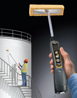
Low voltage holiday detection is used on coatings that are less than 20 mils (500 µm) in thickness. A wet-sponge detector (available from various manufacturers) consists of a wand containing a metal end-clamp with a cellulose sponge that is saturated with tap water, a ground cable that is connected to an uncoated area on the structure, and a detection unit that will audibly alarm if any pinholes or holidays are detected. The voltage setting for coatings on steel is constant (67.5v); however, some units offer a 90v setting for less conductive substrates such as concrete.
Prior to performing the inspection, a Functional Verification should be performed to verify the detector is operating correctly. Functional Verification is discussed a little later in this article.
A ground wire from the detector unit is clamped to the structure. This clamp must be in direct contact with the uncoated substrate and not the coating (the coating will act as an insulator). It may be necessary to remove a small amount of coating to expose the substrate to attach the ground wire, with the area marked for repair. The cellulose sponge is saturated with tap water, then traversed across the coated surface in a consistent pattern at a rate not to exceed one lineal foot per second. If a pinhole or holiday is present, the water from the sponge penetrates to the unprotected substrate, completing the circuit to the detector. When the circuit is completed, the detector will produce an audible and visible signal. The void is marked for repair using a removable material such as painter’s tape or chalk. Many detectors are available with a headset port for use in noisy locations.
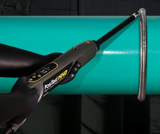
High Voltage (spark) Detection
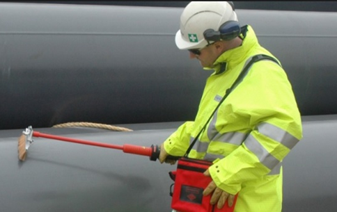
High voltage (spark) detectors (available from various manufacturers) are used on coatings/linings greater than 20 mils (500 µm) in thickness, although they may also be used on coatings/lining as thin as 10 mils (250 µm) provided the voltage is set correctly. The process is similar to low voltage testing, however metal brushes (stainless steel or brass, pictured), Neoprene rubber, or coil electrodes (pictured) are employed instead of a sponge, and the voltage setting must be calculated and entered onto the detector unit prior to use. A ground cable connects the detector to the structure to complete the circuit. An audible/visible alarm will be heard/seen, and a spark will often be visually observed as a holiday or pinhole is detected. When used on pipelines, if the pipe is grounded to earth, the ground cable can be dragged across the soil, rather than connected directly to the pipe (provided continuous contact with the soil is maintained).
Prior to performing the inspection, a Functional Verification (discussed in the next section) should be performed to verify the detector is operating correctly.
Calibration, Verification of Voltage Output, and Functional Verification of Holiday Detectors
Like many coating inspection instruments, calibration, field verification, and proper operation are critical steps before use. These steps for holiday detectors are briefly described below.
Calibration: For low and high-voltage holiday detectors, annual calibration is performed by the instrument manufacturer or an accredited calibration laboratory under controlled conditions. A Certificate of Calibration is issued, and a due date sticker is frequently attached to the detector. If the detector is not producing the correct voltage output (i.e., outside of tolerance), it should be repaired or replaced.
Verification of Output Voltage: Verification of the output voltage and overall function should be performed before and after each period of use, if the detector has been dropped, or if the electrode or coating thickness changes. Note that most low voltage (wet sponge) detectors are preset to 67.5 or 90 volts and have a button that the user pushes to verify the detector is operating properly. This is the extent of the field verification.
To perform a two-point Verification of Output Voltage on a high voltage detector, ensure that the detector is properly grounded to the structure, and that the electrode to be used for testing is connected and in contact with the coating to be tested. Connect the ground from a high-voltage voltmeter to the grounding clip from the detector. Turn the detector on, set the voltage based on the expected/measured low coating thickness, and activate the voltage output. While the voltage output is activated, place the electrode of the voltmeter against the detector’s electrode. The measured voltage on the voltmeter should be within 10% of the desired test voltage. If required, adjust the test voltage setting on the detector and reverify, then repeat this procedure based on the expected/measured high coating thickness. Note that some high-voltage holiday detectors contain an integrated voltmeter and means of adjusting the test voltage at the electrode automatically, thereby performing these steps automatically.
Functional Verification: To perform a functional verification, locate a known holiday in the coating, where a small area of the substrate is exposed. Verify that the detector is properly grounded, then place the wetted sponge (low voltage detectors) or electrode (high voltage detectors) on the coating at least 1-inch away from the known holiday. Power-up the detector, activate the voltage output (high voltage detectors), and pass the sponge or electrode across the known holiday and ensure that the alarm activates.
Selecting the Correct Voltage Setting
Voltage selection when performing high-voltage holiday detection is very critical. If the voltage is set too high and exceeds the dielectric strength of the coating it can adversely affect long-term performance. Conversely if the voltage is set too low, holidays may not be detected and that too can impact long-term performance of the coating/lining, as well as the integrity of the asset itself. For decades we were taught that the voltage setting is based on a rule of thumb of 100 volts per mil of coating. However, standards published by NACE International and ASTM International never referenced this rule of thumb, but rather contained a formula for calculating the proper test voltage, which is shown below (there are alternate M values for coating thickness expressed in millimeters):
V = M*(Sq. Root of coating thickness)
Where:
V = Voltage Setting
M = 525 (for coatings less than 40 mils thick)
1250 (for coatings equal to/greater than 40 mils thick)
The current versions of ASTM D5162[1] and NACE SP0188[2] (and previous versions of ASTM G62[3]) all contain this formula. Extensive research conducted by Avid Protective Products, Inc. and Tnemec Company, Inc. published/presented at the AMPP 2022 Annual Conference and subsequently the Journal of Protective Coatings and Linings in September 2022[4] revealed that these formulas, the Suggested Voltage Setting tables in the standards, as well as the “rule-of-thumb” all produced voltage settings that were too low and there was concern that pinholes/holidays would go undetected.
In response to this groundbreaking research, work began on revising industry standards for holiday detection published by both ASTM and AMPP. ASTM G62 now incorporates a new method of calculating the inspection voltage based on Paschen’s Law, which states that the test voltage shall be 1.5 times the dielectric strength of air at the measured dry film thickness as calculated using Paschen’s law, plus 1500 volts (V). For air at standard atmospheric temperature and pressure, the voltage is calculated as:
![V=1500+1.5[170+63.0d+293√(d )]](https://kta.com/wp-content/uploads/2023/10/Equation-for-CCIF-11.png)
Where V equals the test voltage, and d equals the coating thickness (mils).
A voltage setting lookup table for common coating thickness values (developed based on the formula above) is provided in Appendix 1 of ASTM G62. NACE SP0188 will hopefully follow a similar path (changes are in-process as of the writing of this column), and revisions to ASTM D5162 will likely get underway in 2024.
The table below compares the “rule of thumb” to previously referenced formulas, and to the latest formula based on Paschen’s Law using two different coating thickness values. Based on this comparative illustration it is evident that voltage settings using the rule of thumb and as currently referenced in NACE SP0188 and ASTM D5162 are significantly lower than the new formula.
| Coating Thickness | “Rule of Thumb” (100v/mil) | Previous Formulas (rounded) | New Formula (Paschen’s Law) |
| 34 mils | 3,400 v | 3,100 v | 7,500 v (221 v/mil) |
| 70 mils | 7,000 v | 10,500 v | 12,000 v (171 v/mil) |
A voltage setting of 1.5 times the dielectric strength of air ensures that factors such as debris on the surface of the electrode or coating, local variations in coating thickness, and imperfections in the electrode are less likely to result in a failure to detect a holiday. However, if efforts are made to account for those factors, and there is agreement among all interested parties, a lower test voltage can be acceptable. For example, a lower voltage setting may be necessary when the calculated voltage is near the dielectric strength of the coating, or the calculated voltage at the measured dry film thickness exceeds the capabilities of available holiday detection equipment. While it is critical that the test voltage selected not exceed the dielectric strength of the coating (or electrical breakdown may occur through the coating, damaging it), for most common coatings used today this is not a concern.
Note that the dielectric strength of the coating is not always listed on the coating manufacturer’s product data sheet, so you may need to contact the technical representative to obtain that value. Also, it is recommended to check with the coating manufacturer for their recommended voltage setting for their coating systems, as some coating formulations may require special voltage settings.
Also, the voltage setting is based on the average dry film thickness. If the thickness of the coating varies substantially, then the use of multiple voltage settings may be required during inspection. For example, if the thickness of the coating on a pipe spool (applied in the shop) is different than the thickness of the coating applied to the girth weld area in the field, then the voltage setting should be adjusted based on actual thicknesses.
Summary
This edition of the Certified Coating Inspector Forum focused on the four W’s of Holiday/Pinhole Detection (What, When, Where, and Why), performing low and high voltage holiday detection, the steps that should be performed prior to testing including calibration and field verification, and the importance of calculating and selecting the proper test voltage when using a high voltage detector. Most importantly, a new formula for calculating the correct voltage setting for high voltage detection based on Paschen’s Law was discussed. It is always a good idea to check with the coating manufacturer for their recommended voltage setting for their coating systems; however, if they advise to use 100 volts/mil you may want to inform them of changes that have been or will be incorporated into industry standards for holiday detection.
[1] Standard Practice for Discontinuity (Holiday) Testing of Nonconductive Protective Coating on Metallic Substrates
[2] Discontinuity (Holiday) Testing of New Protective Coatings on Conductive Substrates
[3] Standard Test Methods for Holiday Detection of Coatings used to Protect Pipelines
[4] Are You Ready for a Holiday? Industry Misconceptions Around Testing for Discontinuity, Cameron Walker, Avid Protective Products, Inc.; and Vaughn O’Dea, Joshua Bell, and Javier Tormes, Tnemec Company, Inc.; JPCL, Volume 39, No. 9, September 2022


Thank you Bill, for the mini- refresher course. I always appreciate reading your instructional information.