THE SUBJECT
Two steel 250-plus-ton, fixed, gantry crane structures were overcoated as part of a 2014 coating remediation project. The cranes are located in the Northeastern U.S. and were erected in 1956. They reportedly still had the original coating system when the remediation was performed. Project specifications called for spot repairs at corroded areas and a full overcoat.
As seen in JPCL, June 2017

THE SPEC
The remediation specification required that general cleaning be performed in accordance with SSPC-SP 1, “Solvent Cleaning” or alternatively, waterjetting in accordance with SSPC-SP 12 (despite it already having been replaced by SP/NACE WJ-1 through 4). Spot repair required removal of all rust and loose, peeling and flaking paints in accordance with SSPC-SP 11, “Power Tool Cleaning to Bare Metal.” Following surface preparation, spot areas were to be primed with an epoxy coat after which the entire structures were overcoated with a three-coat paint system consisting of a 100-percent-solids epoxy sealer, a two-component high-solids self-priming epoxy intermediate coat and an aliphatic polyurethane finish coat. The epoxy sealer was specified to be applied at a dry-film thickness (DFT) of 1.5 mils, the epoxy intermediate coat at 4-to-8 mils DFT and the polyurethane finish coat at 2-to-5 mils DFT.
The specification contained information indicating that adhesion testing was required prior to surface preparation and that the coating adhesion results were good with levels ranging from 3A to 4A on most surfaces. The specification further indicated that the existing intact coatings shall be overcoated as specified.
PRE-APPLICATION TESTING
An initial test patch of the epoxy sealer was reportedly applied to the structures prior to overcoating. The application of the epoxy sealer reportedly caused the existing, original silver topcoat to fracture cohesively and disbond. A second test patch was reportedly applied with the epoxy intermediate coat directly to the existing silver topcoat without the epoxy sealer coat. This second test patch was reported to be acceptable. The test-patch applications and testing were not documented. Coating operations began in the fall of 2014.
Areas of spontaneous delamination were observed at some point after completion of the coating work. As a result of the delamination, a coating consulting firm was contacted to provide an independent investigation of the problem.
FIELD INVESTIGATION
A field investigation was conducted to establish what processes or procedures were actually performed in the field. Background information is rarely sufficient to tell the whole story of what occurred or was done during project execution. The following examinations and tests were performed by the investigator.
Visual Examination
A visual assessment of the quantity and distribution of disbonding and other visible coating deterioration on the coated surfaces was performed.
Coating Thickness
Total coating-system thickness was measured using a Type 2 digital gage which non-destructively measures non-magnetic coating thickness over ferrous substrates using a magnetic principle. Accuracy of the instrument was verified prior to and after use as per National Institute of Standards and Technology (NIST) traceable coating-thickness standards.
Number of Coats
The number of coating layers and the thickness of each individual layer were determined in the field using a Tooke gage with a 2x tip in general accordance with ASTM D4138, “Standard Practices for Measurement of Dry Film Thickness of Protective Coating Systems by Destructive, Cross-Sectioning Means.” Tooke gage examination involves scribing through the coating system with a beveled cutting tool and then examining the cut through the eyepiece of the gage. The optics of the gage provide 50-times magnification and the eyepiece contains a calibrated reticle for measuring the apparent width of each visible coat. It should be noted that adjacent coating layers of the same or similar color may not be differentiated by Tooke gage examination.
Coating Adhesion
Coating adhesion testing was conducted in accordance with Method A of ASTM D3359, “Standard Test Methods for Rating Adhesion by Tape Test.” Method A involves making two intersecting cuts through the coating to the substrate with the smaller angle of the cuts between 30 and 45 degrees. A special pressure-sensitive tape is then applied to the X-cut area and rapidly removed. The adhesion is rated in accordance with the ASTM rating scale from 5A to 0A. Ratings of 4A to 5A are typically considered to represent good adhesion, 2A to 3A represent fair adhesion and 0A to 1A represent poor adhesion. ASTM D6677 requires making a similar “X” cut through the coating and probing the intersection with a knife to determine the ease or difficulty of removal on a scale from 0 (easy) to 10 (difficult).
Coating Samples
Samples of the coating system were taken at disbonding and intact areas for further laboratory analysis. Sample removal from what appeared to be non-failing, intact coating began failing (disbonding) during sample removal.
Photographs
Photographs of typical coating conditions observed were taken.
VISUAL EXAMINATION
The coating system on the structures appeared to be in good condition with the exception of the spontaneously disbonded areas. Areas without disbonding appeared smooth and continuous. The coatings on the structures had spontaneously delaminated on approximately 5-to-15 percent of the surface area. In areas where the coating system delaminated, a silver coating (presumably the existing topcoat prior to overcoating) was attached to the back side of the disbonded paint chips but was also present on the substrate, indicating a cohesive break. Small spots of the original orange primer were also sporadically observed on both the back sides of the paint chips and on the substrate surfaces. Areas of spontaneous disbonding were randomly scattered over the surface with no noticeable pattern to the failure. All disbonded areas exhibited a cohesive failure within the original silver topcoat layer.
COATING THICKNESS
Coating thickness measurements were performed at random locations both near the disbonding areas and in areas without visual signs of disbonding. The total system thickness values ranged from 14 to 27 mils with an average thickness of approximately 20 mils. Thickness values were consistent in all areas tested. Measurements performed on the coating remaining on the surface in areas where disbonding had occurred ranged from 3 to 8 mils.
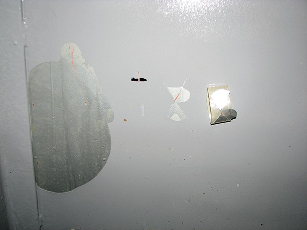
Coating thickness measurements of individual coats obtained using a Tooke Gage revealed four layers of paint on the surfaces consisting of an orange-colored primer, a silver intermediate coat, a gray intermediate coat and a gray topcoat. The thickness of each layer was 2-to-3 mils of the orange, 8 -to-10 mils of the silver, 4-to-5 mils of the gray intermediate and 2-to-4 mils of the gray topcoat. The orange primer and the silver layer were the original existing coating system.
COATING ADHESION
Adhesion testing was performed in accordance with ASTM D3359 and ASTM D6677, “Standard Test Method for Evaluating Adhesion by Knife” in areas adjacent to disbonded coatings and in areas where spontaneous disbonding was not observed. The adhesion was rated poor — 0A for all areas tested using tape and 0 for all areas tested by knife. All of the tested areas showed a cohesive failure in the original silver topcoat with silver coating on both the back side of the paint chips and substrate. The overcoat system was adhered to the top portion of the original silver topcoat and the remaining silver and orange layers were well-adhered to the substrate.
COATING SAMPLES
Several representative field samples from both failing (delaminated) and non-failing areas were obtained during the field visit. Further analysis of the field samples was performed by a laboratory specializing in coating-failure analysis.
LABORATORY INVESTIGATION
The laboratory investigation consisted of visual and microscopic examination and infrared (IR) spectroscopy. The test methods employed and results of the investigation follow.
Microscopic Examination
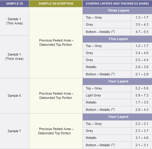
Microscopic examination of the samples was conducted using a digital microscope with 200-times magnification. The samples had between three and four coating layers. The range of the thicknesses of the individual layers and the magnification at which the data was collected are shown in Table 1.
Infrared Spectroscopy
IR spectroscopic analysis was performed with a Fourier transform infrared spectrometer. Sample scrapings from the silver metallic coating were combined with potassium bromide powder and formed into a pellet under high pressure. The pellet was then placed in the optical path of the spectrometer and a spectrum was obtained over the range of 4,000 to 400 cm-1.
This analysis revealed that the spectrum is consistent with spectra produced by aged alkyd materials. A styrene modification of the resin material was also indicated.
DISCUSSION
Field adhesion testing and the laboratory analysis of paint chip samples indicated that the failure of the coating system on the structures was a result of degradation and poor cohesive qualities within the original alkyd silver topcoat.
The laboratory investigation found the IR spectra was consistent with an aged alkyd highly pigmented with aluminum. Industry experience with formulations of alkyd coatings has shown that over time, environmental exposure such as UV exposure or wet/dry/thermal cycling can degrade the alkyd resin. Additionally, because alkyds cure by oxidation (meaning they react with oxygen in the air), the end point of the cured system is a highly oxidized, brittle coating film. Aged alkyd films may show no visible signs of weakness and seem to be “paintable,” but when the weakened film is painted over, the contractive forces (curing stresses) that occur naturally as the new film dries and cures put added tension on the aged and weakened paint film. Each additional overcoat adds stress from curing, as does the additional weight of the new overcoat system. Ultimately, the paint system fractures at its weakest link, which in this case meant cohesively within the original aged layer. The number of coating layers, the thickness of coating layers and the curing stress of each new layer contributed to the failure of the aged film. Additional complications in this case involved the presence of the aluminum pigments, which can also become oxidized, creating a weak surface layer.
Requiring test patches was appropriate for this project and the results should have identified the problems associated with overcoating this material, so it is not clear why there was cohesive failure on the test patch within the original silver topcoat when the epoxy sealer was used, but an absence of a cohesive failure when the epoxy sealer was not used. When conducting test-patch assessments, all coating layers being overcoated should be included, such as the existing finish as well as the exposed primer, and should also include a few candidate coating materials. Test patches also present an opportunity to evaluate alternative surface preparation techniques — for example power washing at a low pressure versus high-pressure water cleaning versus SSPC-SP 7/NACE No. 4, “Brush-Off Blast Cleaning.” In environments with broad temperature swings between seasons, a long-term test patch should be considered. Guidance on the preparation and evaluation of test patches is found in ASTM D5064, ”Standard Practice for Conducting a Patch Test to Assess Coating Compatibility.”
The painting contractor indicated that surfaces were cleaned by power washing. Inspection documents provided for review suggested that the surface preparation met the manufacturer’s requirements and was signed off on by the Contractor’s QC and the Owner. Despite the documentation, the surface preparation performed was not adequate to remove the weak silver layer. It can also be questioned whether or not overcoating was the appropriate maintenance strategy for this project due to the difficulty of removing the weak surface layer and oxidized aluminum.
 Rob Lanterman is a coatings consultant with KTA-Tator, Inc. He is an SSPC-certified Protective Coatings Specialist and a NACE Level-3 certified Coating Inspector with over 18 years of coatings engineering experience.
The bitterness of poor quality remains long after the sweetness of low price is forgotten.
Indeed. Thank you for reading.
Do you have an opinion about overloading on this type of structure or to blast and replace the entire system?
All coating failures have as origin;
– incorrect specification,
– poor adhesive (poor workmanship quality),
– poor cleanliness.