KTA’s Certified Coating Inspector Forum Volume 3, Issue No. 11 – November 2024
William Corbett, COO
AMPP Senior Certified Coating Inspectors & Certified Protective Coating Specialists
KTA’s Certified Coating Inspector Forum is designed to provide professional development/continuing education on standards, inspection practices, new instruments, and other topics to help keep certified AMPP and FROSIO coating inspectors current. It represents the views of the author and KTA-Tator, Inc. It may or may not represent the views of AMPP: The Association for Materials Protection & Performance, even though SSPC, NACE, and AMPP standards are frequently referenced in the content.
Introduction
For this edition of the KTA Certified Coating Inspector Forum, I describe the test methods and instruments used to determine the presence of moisture in cementitious walls and floors, compare the depth of moisture detection for each of the methods and the reporting units, and explain the recommended frequencies for moisture testing.
Concrete needs moisture (water) to cure. But once concrete achieves both the required tensile and compressive strength, the residual water in the concrete, if high enough in concentration and the coating is applied before ample evaporation occurs, can be detrimental to the performance of the coating system. Likewise, properly cured coatings can be damaged from water that enters the concrete from external sources. As water attempts to leave the concrete it becomes trapped beneath the coating system, which in time, can cause the coating to blister and disbond. While some coatings have adequate permeance to allow water vapor to pass through, many coatings will trap liquid moisture and prevent it from evaporating.
Sources of Moisture
Sources of moisture in concrete include construction practices (e.g., leaving CMU [concrete masonry unit] block open to rainfall); leaking roofs; defective control joints flashing, and sealants; water vapor trapped in wall cavities; wind-driven rain; pressure washing; and ground water beneath floor slabs.
Effects of Entrapped Moisture on Coating Performance
The presence of excessive moisture in concrete can cause efflorescence (a whiteish, salt deposit that collects on the surface of concrete, brick, stone, stucco, and other building materials when water passing through the concrete evaporates, leaving salt deposits on the surface), blistering, peeling, and overall poor film integrity. Coating concrete without first verifying that detrimental moisture is not present, can result in catastrophic failure of the applied coating.
Industry Standards
ASTM International has six standards that focus on measuring moisture in concrete (listed below in alpha-numerical order), written primarily for floors:
ASTM D4263, Standard Practice for Indicating Moisture in Concrete by the Plastic Sheet Method (addresses both walls and floors)
ASTM F710, Preparing Concrete Flooring to Receive Resilient Flooring
ASTM F1869, Standard Test Method for Measuring Moisture Vapor Emission Rate of Concrete Subfloor Using Anhydrous Calcium Chloride
ASTM F2170, Standard Test Method for Determining Relative Humidity in Concrete Floor Slabs Using in situ Probes
ASTM F2420,Standard Test Method for Determining Relative Humidity on the Surface of Concrete Floor Slabs Using Relative Humidity Probe Measurement and Insulated Hood
ASTM F2659, Standard Guide for Preliminary Evaluation of Comparative Moisture Condition of Concrete, Gypsum Cement and Other Floor Slabs and Screeds Using Non-Destructive Electronic Moisture Meter
In addition, SSPC-Guide 23, Field Methods for the Determination of Moisture in Concrete and Masonry Walls and Ceilings, EIFS, and Stucco adapts the ASTM floor moisture measurement standards for use on walls, except for the anhydrous calcium chloride and insulated hood methods, which do not work on vertical surfaces.
Review of Common Test Methods
Brief explanations of the methods for testing moisture in concrete included in SSPC-Guide 23 are provided. It is important to read and follow the respective test method and instrument instructions as the summaries below only provide an overview.

Method 1 – Plastic Sheet Method: A minimum 18” x 18” (457 x 457mm) sheet of 4 mil (0.1mm) or thicker polyethylene is obtained, and the perimeter of the plastic sheet is taped to the surface (note the shape change on CMU in Figure 1 to create a better seal along the mortar joints. The variation in shape is acceptable provided it covers the same minimum surface area). The plastic remains in place for a minimum of 16 hours (and ideally 22 to 26 hours, i.e., from morning to morning) and the underside of sheet or the surface is
A variation to this method is described in Appendix X2.4.4.3 of ASTM F710 and involves using a moisture meter (electrical impedance, radio frequency, or electrical conductivity, all described later) before attaching the sheet, then again immediately upon removal of the sheet. If the second reading is significantly higher than the first, it’s an indication that moisture is present.
Here are four precautions when performing the plastic sheet test:
- If the surface being tested is coated with a low permeance coating, it may provide a barrier to the evaporation of moisture, providing misleading results.
- Before installation of the plastic sheet, allow the surface to dry after a rain event (2 to 24 hours) or after visible evaporation of dew (minimum 4 hours).
- If significant rainfall occurs during the test period, the results may be void.
- Loss of adhesion of the tape securing the perimeter of the plastic can void the test.
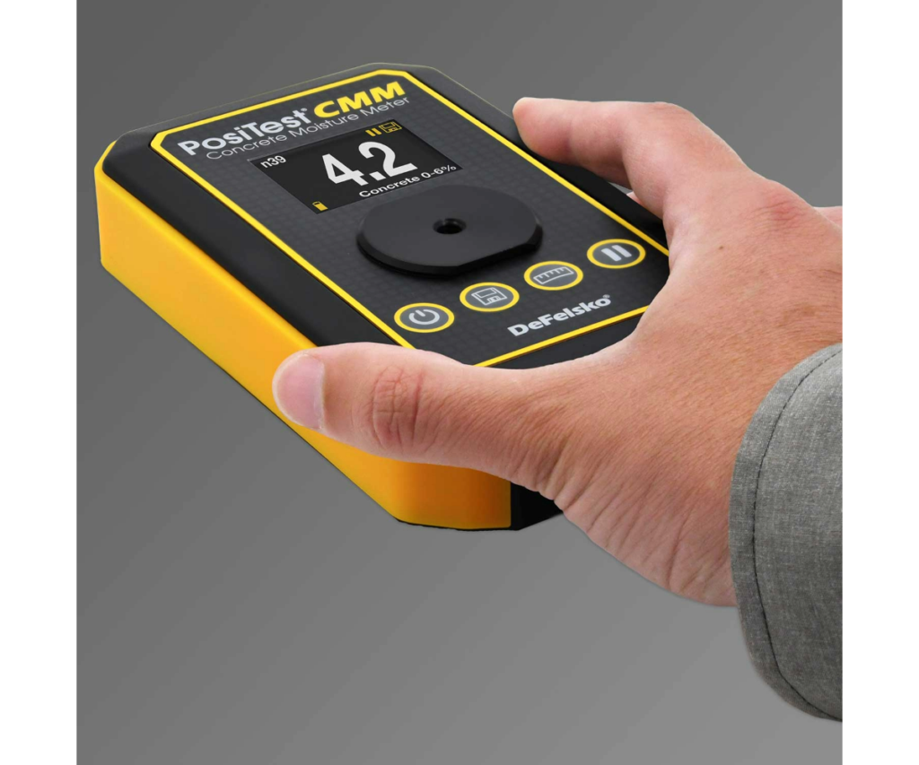
Method 2 – Electrical Impedance Meter: The electrical impedance of the concrete is measured by transmitting an alternating electric field from one end of the instrument, through the substrate, to the other end of the instrument (Figure 2). The electrical impedance of a material varies in proportion to its moisture content. The results are displayed as % moisture content (typically from 0 to 6%). An electrical impedance meter is the only instrument that directly provides the percent moisture in concrete.
Direct contact with the substrate is required so there is no loss of signal sensitivity. Any existing paint should be removed before testing, but SSPC Guide 23 includes a procedure for determining the effect that paint may have on the results. This procedure involves taking readings through the paint in a 6” x 6” area, mechanically removing the paint, obtaining another set of readings in the same area, and comparing the results to determine the effect of the paint. Once this effect is known, it may not be necessary to remove the paint in subsequent test locations.
Before using an electrical impedance meter, allow surface to dry after a rain event (2 to 24 hours) or after visible evaporation of dew (minimum of 4 hours).
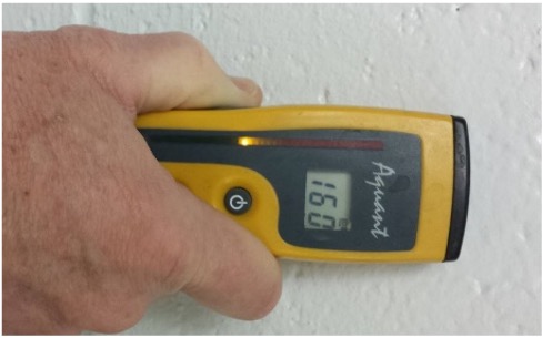
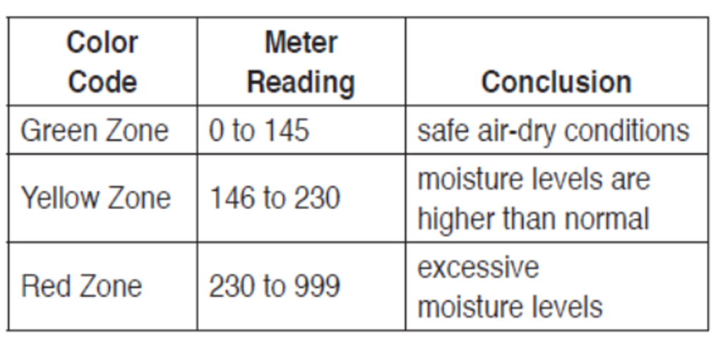
Method 3 – Radio Frequency Moisture Meter: This type of instrument (Figure 3a) can detect moisture through existing paint. The results are displayed on a relative scale, rather than percent moisture. One manufacturer displays the results on a scale from 0 to 999. The relative moisture content represented by the readings is shown in Figure 3b, below).
Here are a few precautions when using this method of moisture detection.
- Allow the surface to dry after a rain event (2 to 24 hours) or after visible evaporation of dew (minimum of 4 hours).
- Certain minerals in masonry can impact the accuracy of the readings (e.g., iron ore deposits and high concentrations of salts in masonry will yield excessively high results).
- Metal surfaces within the range of the sensor can yield high results (e.g., door frames, wire reinforcement in mortar joints).
- The instrument must be in complete contact with the surface (no air gaps). If not, results may be lower than actual.
Method 4 – Electrical Conductivity (Resistance) Meter: This instrument measures the electrical conductivity of the substrate between two electrodes (Figure 4a). The conductivity varies in proportion to the moisture content.
There are several measurement options:
- Surface measurement: Either press the ¾” pin electrodes directly against the surface or drive masonry nails ¼” into the substrate and touch the pin electrodes to nail heads.
- For measurements in the concrete, drill two holes to the desired measurement depth and insert nails into the holes with care to avoid hitting the sides and touch the pin electrodes to the nail heads. To better assure that sides of the nails aren’t touching the concrete, the shafts can be wrapped with vinyl electrical tape, leaving only the tips exposed. One manufacturer also supplies 3 1/4” probes for use in insulation that could be inserted into the holes. Steel rods can also be wrapped in vinyl electrical tape, with the tips exposed, to assess moisture deeper into the concrete. Figure 4b shows rods being used to determine the presence of moisture in core-fill insulation within the cells of CMU.
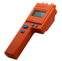
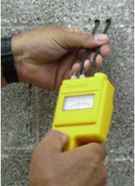
The results are displayed on a relative scale, rather than percent moisture (a scale from one manufacturer [Figure 4c] is shown below).
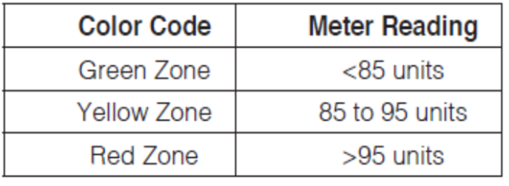
Figure 4c
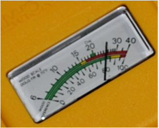
Method 4 has the same list of precautions as Method 3. In addition, the scale on older models of this type of detector (Figure 4d) is frequently used incorrectly. It is often assumed that the top scale was percent moisture and problems could occur when moisture content was 15% or greater. Problems with concrete can occur at less than 5% moisture. The top scale is percent, but it’s for wood only, and 15% for wood is a sound threshold. The bottom scale is for concrete, and it is an arbitrary scale only. As indicated in Figure 4c, the numbers are “units” not percent. There is no correlation between percent moisture (top scale for wood) and the amount of moisture in concrete (bottom scale).
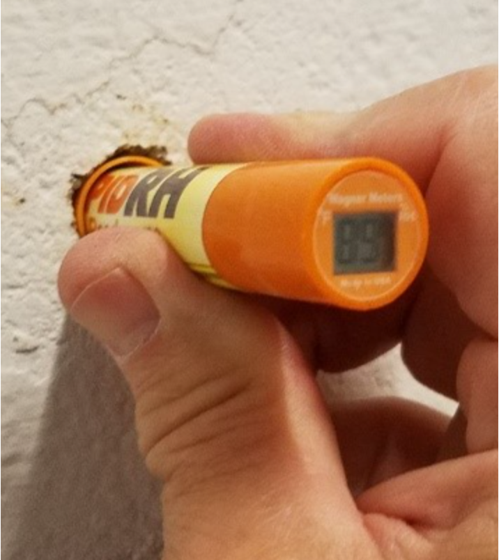
Method 5 – Relative Humidity (RH) Probes: For this method, 3/4” or 5/8” diameter holes (depending on the manufacturer), are drilled into concrete to a specific depth, and a plastic tube or liner is inserted, and capped (Figure 5). After the relative humidity of the air space in the hole reaches equilibrium, the RH is read using specialized instruments. SSPC Guide 23 indicates that equilibrium is reached after 72 hours, but that shorter times may be used if agreed upon by the instrument manufacturer and purchaser. Note that ASTM F2170 for using the RH instruments on floors was revised in 2019 to reduce the time from 72 hours to 24 hours.
The hole needs to be deep enough to provide a representative assessment of humidity, and the depth is affected by the drying conditions of the concrete structure.
ASTM F2170 provides guidance for the depth of holes in slabs, which may be of help when measuring walls:
- When drying from one side of the slab, the measurement depth is 40% of the depth of the slab; when drying from both sides of the slab, the measurement depth is 20% of the depth of the slab.
Here are a few precautions when using this method of moisture detection.
- Allow the surface to dry after a rain event (2 to 24 hours) or after visible evaporation of dew (minimum 4 hours).
- When used on floors, the ASTM standard requires that the temperature of the probe and temperature of the concrete be the same at the time of testing (allow the temperature of the probe to reach equilibrium).
- There are no standards that establish the effect of outdoor conditions (e.g., rain, direct sunlight) on the results, but RH probes have been used to determine the approximate RH of stable dense walls.
Frequency of Measurements, Suitability of Methods Based on Substrate Type, Depth of Measurement, and Reporting Units
Tables 1, 2 and 3 in SSPC-Guide 23 discuss the frequency of measurements, the suitability of the test methods for different substrate types, the depth that moisture within the concrete is determined, and the reporting units for each of the methods described in this article. The excerpted tables are shown below:
Table 1 in SSPC-Guide 23 (below) provides suggested testing frequencies for walls prior to coating.
| Area Being Coated in a Given Day | Method 1 Plastic Sheet* |
Method 2 Impedance |
Method 3 Radio Frequency |
Method 4 Conductivity |
Method 5 RH** |
|---|---|---|---|---|---|
| ≤ 10 m² (≤ 1000 ft²) |
3 tests | Locate test zones every 7 to 10 m (25 to 35 ft) of wall, and test at 3 heights within each zone. | Locate test zones every 7 to 10 m (25 to 35 ft) of wall, and test at 3 heights within each zone. | Locate test zones every 7 to 10 m (25 to 35 ft) of wall, and test at 3 heights within each zone. | Same as Method 1 |
| 11 to 500 m² (1001 to 5000 ft²) |
5 tests | ||||
| 501 to 1000 m² (5001 to 10,000 ft²) |
10 tests | ||||
| > 1000 m² (>10,000 ft²) |
10 tests for first 1000 m² (10,000 ft²) plus 1 test for each additional 175 m² (2,000 ft²) |
||||
|
* Test frequency differs from recommendations in ASTM D4263. ** One probe in cavity and one probe in mortar joint in each location. |
|||||
Table 2: Suitability of Test Methods by Substrate Type (from SSPC-Guide 23)
| Substrate Types/Textures | Method 1 Plastic Sheet |
Method 2 Impedance |
Method 3 Radio Frequency |
Method 4 Conductivity* |
Method 5 RH Probe |
|---|---|---|---|---|---|
| Poured Concrete/Tilt up | Good | Good | Good | Good | Good |
| Precast – smooth | Good | Good | Good | Good | Good |
| Precast – textured | Marginal | Poor | Good | Good | Good |
| Smooth CMU | Good | Good | Good | Good | Good |
| Split-faced CMU | Marginal | Poor | Marginal | Good | Good |
| Grout (when surrounded by block) | Good | Poor | Good | Good | Good |
| EIFS, Stucco | Good | Good | Good | Good | Good |
| Painted Surfaces | Marginal | Marginal | Good | Good | Good |
| * Conductivity method performance may vary based on substrate characteristics. | |||||
Table 3: Moisture Content Depth and Reporting Units (from SSPC-Guide 23)
| Measurement Characteristics | Method 1 Plastic Sheet |
Method 2 Impedance |
Method 3 Radio Frequency |
Method 4 Conductivity* |
Method 5 Relative Humidity |
|---|---|---|---|---|---|
| Substrate Depth | Bulk | Top 25 mm (1 inch) | Top 19 mm (3/4 inch) | Surface* | Bulk |
| Reporting Units | None (visual) | % moisture (relative scale) | Relative Scale | Relative Scale | % of moisture Saturation |
As a point of comparison with the test frequencies for walls in SSPC-Guide 23, following is a summary of the test frequencies for floors as presented in the relevant ASTM standards.
| Method | Frequency |
|---|---|
| Plastic sheet (ASTM D4263) | Walls: 1 per 500 sq. ft.; 1 for every 10-foot rise, starting within 1 foot of floor. Floors: 1 per 500 sq. ft. |
| Electrical Impedance (ASTM F2659) | Floors: ≥8 tests for first 1,000 sq. ft.; ≥5 tests for each additional 1,000 sq. ft. Test across floor, including center and within 3 feet of each exterior wall. |
| Radio Frequency (ASTM F2659) | Floors: Same as electrical impedance above |
| Conductivity (ASTM F710) | Floors: Not addressed, but same frequency as electrical impedance seems appropriate. |
| RH probes (ASTM F2170) | Floors: ≥3 tests for first 1,000 sq. ft; ≥1 test for each additional 1,000 sq. ft. At least one test within 3 feet of each exterior wall. |
Anhydrous Calcium Chloride (Floors)
A final method of testing for moisture in concrete floors, but not walls, is the Anhydrous Calcium Chloride test. For this method a known area of bare concrete is exposed to a known weight of anhydrous calcium chloride under a sealed dome for 60-72 hours (Figure 6). The anhydrous calcium chloride is reweighed after exposure and the weight gain is converted to moisture vapor emission rate (MVER) expressed as:
Pounds of moisture, per 1000 ft², per 24 hours
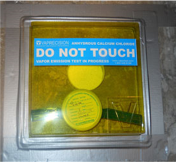
The space above the floor should be at the same temperature and RH as expected during normal use. If that’s not possible or when the service environment involves temperature or RH extremes (e.g., a cold storage room), maintain 75°F ± 10°F and 50% ± 10% relative humidity for 48 hours prior to and during testing.
If the floor is bare, roughen the surface by grinding to create a slight profile equal to ICRI CSP-1 (acid etching) to CSP-2 (grinding) and remove all dust. The intent is to create a profile equivalent to acid etching or grinding, but it is not recommended to do acid etching. The water used for the acid etching/rinsing process could still be present and bias the results, even when waiting 24 hours.
If coatings or floor coverings are present, remove the coating/flooring in a 20”x20” area, roughen the surface to ICRI CSP-1 to CSP-2, remove the dust, and wait 24 hours before testing.
Here are the steps in sequence:
- Weigh the sealed container of anhydrous calcium chloride on a scale to the nearest 0.1g
- Remove the lid from the container and center it under the dome supplied with the kit. Save the blue sealing tape and lid since they will be needed for the post-weighing step.
- Firmly seal the perimeter of the dome to the floor
- Leave the calcium chloride in place under the dome for 60-72 hours.
- Remove the dome and the container, replace the container lid, reattach the tape and reweigh the container to the nearest 0.1 gram using the same scale as was used for the pre-weight.
- Use the formula below (from ASTM F1869) to determine the MVER (moisture vapor emission rate).
MVER (in pounds/1000 ft2/24 hours) =
where:
- ∆M= change in mass (weight gain) of the anhydrous calcium chloride in grams
- A= exposed area of the concrete inside the sealed flanged cover in ft2 after deducting the contact area of the anhydrous calcium chloride dish, and
- T= exposure time in hours
The recommended frequency of testing is 3 locations for the first 1,000 square feet and one location for each additional 1,000 square feet or fraction thereof. In the absence of any manufacturer recommendations, ASTM F710 recommends a maximum of 3 pounds/1,000 ft²/24 hours MVER (for resilient flooring).
Summary
Coating concrete that contains high moisture/water content can result in coating failure. There are several methods/instruments for measuring the moisture content of concrete prior to coating. This article identified potential sources of moisture and described six methods that may be used to measure moisture content along with precautions. It also highlighted the suitability of the various methods based on substrate type, the depth of moisture content measurement and reporting units based on the method of measurement and described various testing frequencies.


The suitability of the various methods of measuring the moisture content of concrete prior to coating are systematically described in detail.
A methodical explanation of all methods.
This is such an important topic that I wish more DIYers understood. We just had a customer that was dealing with some bad efflorescence in his courtyard as a result someone assuming the area was dry when it wasn’t.
Excellent information, the importance of the different methods for measuring moisture in concrete.
Thank you for reading!