KTA’s Certified Coating Inspector Forum Volume 3, Issue No. 13 – Special Bonus Edition
William Corbett, COO
AMPP Senior Certified Coating Inspector & Certified Protective Coating Specialist
KTA’s Certified Coating Inspector Forum is designed to provide professional development/continuing education on standards, inspection practices, new instruments, and other topics to help keep certified AMPP and FROSIO coating inspectors current. It represents the views of the author and KTA-Tator, Inc. It may or may not represent the views of AMPP: The Association for Materials Protection & Performance, even though SSPC, NACE, and AMPP standards are frequently referenced in the content.
Introduction
The November 2023 edition of the KTA Certified Coating Inspector Forum described proposed changes to longstanding industry standards on holiday/pinhole detection. Since that column was published, four of the five most common industry standards for performing holiday detection have been revised and published. Most significantly, these four standards are fully aligned regarding the formulas for calculating the correct test voltage when performing high voltage holiday detection on nonconductive coatings applied to conductive substrates. This column highlights the major changes to those standards.

Change is never easy, nor is it quickly recognized/adopted. No doubt you will continue to hear or read references to “100 volts/mil” as the recommended voltage setting for high voltage holiday detection. You will hear or read that high voltage detection can only be used on coatings over 20 mils thick, even though the standards have been revised to allow it to be used on coatings as thin as 10 mils. You will also hear concerns over “burning through the coating” because the voltage settings have increased under the new formulas when in fact, most of today’s coatings (that would be subject to holiday detection) have a dielectric strength exceeding 500 volts per mil. That is, a 20-mil coating can be tested using 10,000 volts (500 v/mil) and remain unharmed (Note: based on the latest standards, the calculated voltage for a 20-mil coating is 5,600 volts, which is only 280 v/mil). In the past, the same coating would have been tested at 2,000 volts (100 v/mil), but significant research conducted and published in 2021/2022 proved that testing a coating/lining using 100 volts/mil will likely result in undetected holidays.
Share this Forum with your peers and customers. Help communicate these important updates so that the performance of coating/lining systems can be improved through better inspection.
Industry Standards
The four industry standards that have been revised (listed in alpha-numeric order) include:
- ASTM D4787, Standard Practice for Continuity Verification of Liquid or Sheet Linings Applied to Concrete Substrates (2024)
- ASTM D5162, Standard Practice for Discontinuity (Holiday) Testing of Nonconductive Protective Coating on Metallic Substrates (2024)
- ASTM G62, Standard Test Methods for Holiday Detection of Coatings used to Protect Pipelines (2023)
- NACE SP0188, Discontinuity (Holiday) Testing of New Protective Coatings on Conductive Substrates (2024)
Note that a fifth standard, ISO 29601, Corrosion Protection by Protective Paint Systems – Assessment of Porosity in a Dry Film has not yet been revised and does not currently align with the four standards listed above. This standard does not contain a formula, but rather a table containing voltage settings based on coating thickness. The voltage/mil varies, ranging from 117 v/mil @ 20 mils to 145 v/mil @ 197 mils. For coating thicknesses ranging from 209-315 mils, the voltage setting ranges from 95 to 139 v/mil. These differ from the voltage settings prescribed in the other four standards.
Review of High Voltage (spark) Detection
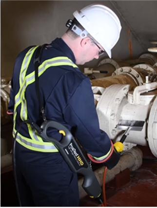
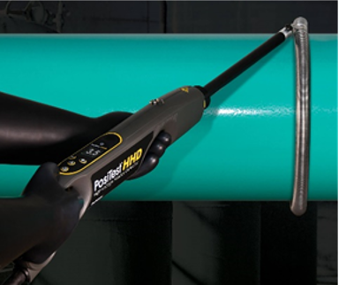
High voltage (spark) detectors (available from various manufacturers) are typically used on coatings/linings greater than 20 mils (500 µm) in thickness, although they may also be used on coatings/lining as thin as 10 mils (250 µm) provided the voltage is set correctly. Metal brushes (stainless steel or brass, pictured left), Neoprene rubber, or coil electrodes (pictured right) are employed, and the voltage setting is calculated and entered into the detector unit prior to use. A ground cable connects the detector to the structure to complete the circuit. When used on pipelines, if the pipe is grounded to earth, the ground cable can be dragged across the soil, rather than connected directly to the pipe (provided continuous contact with the soil is maintained). An audible/visible alarm will be heard/seen, and a spark will often be visually observed as a holiday or pinhole is detected.


Calibration, Verification of Voltage Output, and Functional Verification of High Voltage Holiday Detectors
Like many coating inspection instruments, calibration, field verification, and proper operation are critical steps before use. These steps for holiday detectors are briefly described below.
Calibration: Calibration is required and is performed by the instrument manufacturer or an accredited calibration laboratory under controlled conditions at the frequency. A Certificate of Calibration is issued, and a due date sticker is frequently attached to the detector. If the calibration procedure indicates that the detector is not producing the correct voltage output (i.e., outside of tolerance), it should be repaired or replaced.

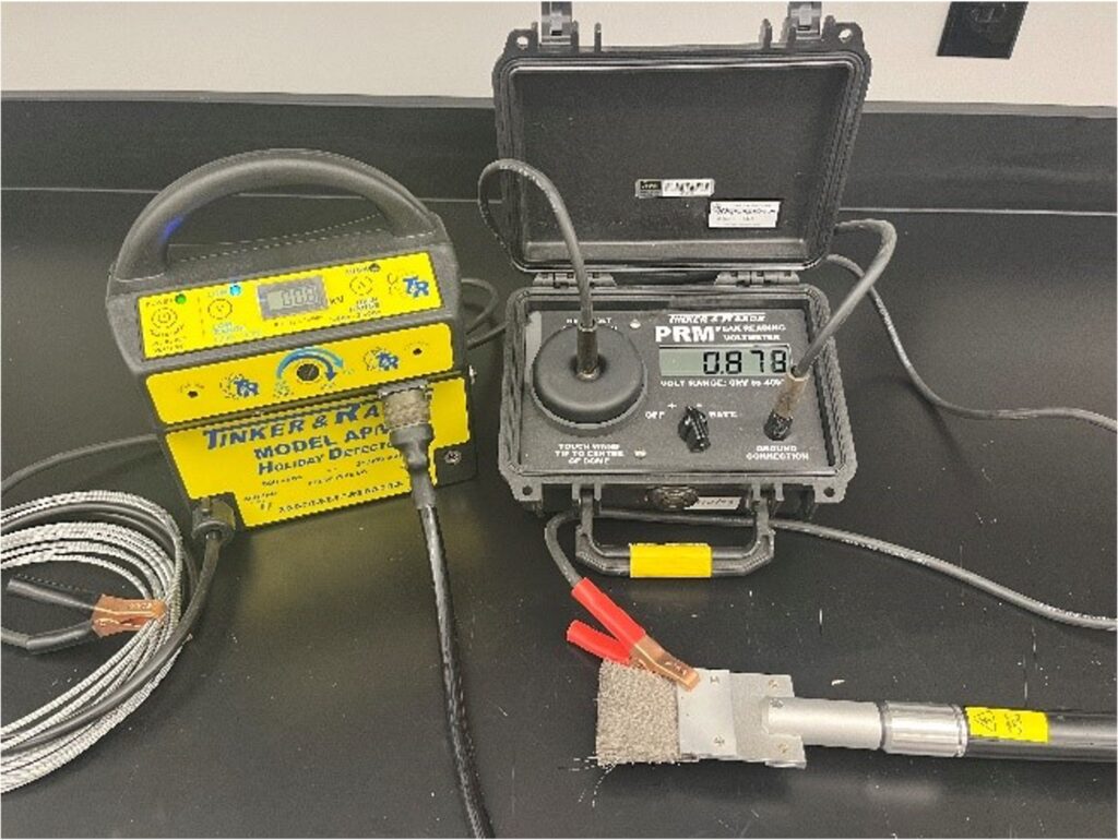
Verification of Output Voltage: Verification of the output voltage and overall function is performed before and after each period of use, if the detector has been dropped, or if the electrode or coating thickness changes significantly. To perform a two-point Verification of Output Voltage on a high voltage detector, ensure that the detector is properly grounded to the structure (direct connection or to the earth in the case of a pipeline that’s grounded), and that the electrode to be used for testing is connected and in contact with the coating to be tested. Connect the ground lead from a peak reading voltmeter to the grounding clip from the detector. Turn the detector on, set the voltage based on the expected/measured low coating thickness, and activate the voltage output. While the voltage output is activated, place the electrode of the voltmeter against the detector’s electrode (the electrode connections from a peak reading voltmeter to the ground cable and detector electrode are illustrated in the photo).
The measured voltage on the voltmeter should be within 10% of the desired test voltage. If required, adjust the test voltage setting on the detector and reverify, then repeat this procedure based on the expected/measured high coating thickness. Note that some high voltage holiday detectors contain an integrated voltmeter and means of adjusting the test voltage at the electrode automatically, thereby performing these steps automatically.
Functional Verification: To perform a functional verification, locate a known holiday in the coating, where a small area (less than 1mm diameter) of the substrate is exposed. If none is visible, a 1mm holiday may need to be created. Verify that the detector is properly grounded, then place the electrode on the coating at least 1-inch away from the known holiday. Power-up the detector, activate the voltage output and pass the electrode across the known holiday and ensure that the alarm activates.
Selecting the Correct Voltage Setting
Voltage selection is very critical. If the voltage is set too high (exceeding the dielectric strength of the coating) it can adversely affect long term performance. Conversely if the voltage is set too low, holidays may not be detected because of the dielectric strength of air and that too can impact long term performance of the coating/lining.

Image courtesy of DeFelsko Corporation
Extensive research conducted by Avid Protective Products, Inc. and Tnemec Company, Inc. published/presented at the AMPP 2022 Annual Conference and subsequently the Journal of Protective Coatings and Linings (JPCL) in September 2022[1] revealed that the formulas and the Suggested Voltage Setting tables in the standards at the time, as well as the 100 volt/mil “rule-of-thumb” all produced voltage settings that were too low and there was concern that pinholes/holidays would go undetected.
Thanks to the groundbreaking research published in 2022, industry standards for holiday detection published by both ASTM and AMPP now incorporate the correct method of calculating the inspection voltage based on Paschen’s Law. The four revised standards now state that the test voltage shall be 1.5 times the dielectric strength of air at the measured dry film thickness as calculated using Paschen’s law, plus 1500 volts (V). For air at standard atmospheric temperature and pressure, the voltage is calculated as:

Where V equals the test voltage, and d equals the coating thickness (mils).
While ASTM D4587-24, D5162-24, G62-23, and NACE SP0188-2024 provide the formula, they also simplify its implementation by including voltage setting lookup tables for common coating thickness values (in both mils and microns). That is, they do the calculations for you. Note that as indicated earlier, ISO 29601 has not yet been updated to align with the other four standards.
The table below compares the “rule of thumb,” previously referenced formulas, and the latest formula based on Paschen’s Law using two different coating thickness values. The differences between the recommended voltages are significant.
| Coating Thickness | “Rule of Thumb” (100v/mil) | Previous Formulas (rounded) | New Formula (Paschen’s Law) |
|---|---|---|---|
| 34 mils | 3,400 v | 3,100 v (91 v/mil) | 7,500 v (221 v/mil) |
| 70 mils | 7,000 v | 10,500 v (150 v/mil) | 12,000 v (171 v/mil) |
A voltage setting of 1.5 times the dielectric strength of air ensures that factors such as debris on the surface of the electrode or coating, local variations in coating thickness, and imperfections in the electrode are less likely to result in a failure to detect a holiday. However, if efforts are made to account for those factors, and there is agreement among all interested parties, a lower test voltage may be acceptable. For example, a lower voltage setting may be necessary when the calculated voltage is near the dielectric strength of the coating, or the calculated voltage at the measured dry film thickness exceeds the capabilities of available holiday detection equipment. While it is critical that the test voltage selected not exceed the dielectric strength of the coating (or electrical breakdown may occur through the coating, damaging it), for most common coatings used today this is not a concern.
Note that the dielectric strength of the coating is not always listed on the coating manufacturer’s product data sheet (PDS), so you may need to contact the technical representative to obtain that value. Also, it is recommended to check with the coating manufacturer for their recommended voltage setting for the coating system, as some coating formulations may require special voltage settings. Be aware that you may be told “use 100v/mil.” When this happens, advise them that industry standards have changed. Many references to industry standards are found in specifications and on PDS without the representative knowing the full content of those standards or realizing that is there have been updates to the standards.
The voltage setting is based on the actual dry film thickness. If the thickness of the coating varies substantially, then the use of multiple voltage settings may be required during inspection. For example, if the thickness of the coating on a pipe spool (applied in the shop) is different than the thickness of the coating applied to the girth weld area in the field, then the voltage setting should be adjusted based on actual thicknesses.
Selecting the correct voltage setting can be challenging given that the applied coating/lining thickness will undoubtedly vary across the surface. For example, if a specification requires a 35-50 mil tank lining, there will likely be areas that have 35 mils and other areas that have 50 mils; both of which meet specification. It is impossible to know the thickness of the coating in every square foot of tank surface (or the appurtenances) or adjust the holiday detector every time the thickness changes. So, let’s look at this a little closer. Based on the new formula using Paschen’s Law, the correct voltage setting for 35 mils is approximately 7,700 volts, which is 220 v/mil; for 50 mils the voltage setting is 9,600 volts which is 192 volts/mil. By taking a conservative approach and setting the detector for the maximum specified thickness (in this case 50 mils, or 9,600 volts), a holiday in the coating lining will be detected independent of the actual coating thickness, up to 50 mils. Some may balk at testing a 35-mil coating at 9,600 volts, however that equates to 274 v/mil. Provided the dielectric strength of the coating is greater than 274 v/mil, the coating will not be damaged by the higher voltage setting. As stated earlier, most coatings today have a dielectric strength exceeding 500v/mil. In fact, ASTM D5162-24 states, “The voltage setting selected is based on the dry film thickness of the coating/lining system. If the thickness of the coating/lining varies substantially, then the use of multiple voltage settings may be required during inspection. Alternatively, select a voltage based on the maximum thickness.”
Follow-up Research
A subsequent article published in the July/August 2024 issue of JPCL[2] discusses updates to the standards and whether there is any risk to coatings associated with the changes to these standards. Here are three key points from the article.
- Coatings and linings are frequently applied by humans and are never perfectly uniform. There will be areas of lower thickness. This infers a corresponding lower dielectric strength of the coating (an assumption of linearity between the coating thickness and dielectric strength of that coating) and concerns that testing a coating at the new voltage requirements will burn through a coating that is comparatively thinner in an area, damaging it. This assumption is incorrect for the thickness ranges of protective coatings. Rather, in most cases as the coating thickness decreases the dielectric strength of the coating increases.
- The author cites a master’s thesis by John Harvey Gustafson on the dielectric strength of some anti-corrosive paints[3]. He combined the data from this thesis with the dielectric values of a dozen industrial epoxy and polyurethane coating systems to estimate the breakdown voltage of materials across thickness ranges. This “data crunch” culminated in an extensive table listing the projected “Burn-through Thickness” when using the new voltage calculation formula. Here’s an example: Based on his data, a 20-mil coating tested at 5,600 volts is estimated to “burn-through” in areas of 4.5 mils or less. A coating less than 25% of the specified thickness is likely going to show evidence of early failure once in service, so detecting these excessively thin locations for repair, even if done through “burn-through” can be beneficial.
- Proper measurement of coating thickness (and repair of areas displaying insufficient thickness) before testing the coating using the new voltage settings poses very little risk to coating damage. Minor variations in coating thickness (from specified) will not be affected by these new holiday detection requirements.
Summary
This Special Bonus Edition of the Certified Coating Inspector Forum described changes to four industry standards for conducting high voltage holiday detection and the importance of calculating and selecting the proper test voltage (based on Paschen’s Law) when using a high voltage holiday detector. While it is always a good idea to check with the coating manufacturer for their recommended voltage setting for their coating systems, if they advise 100 volts/mil, you should inform them of changes that have been made to industry standards for holiday detection. Using the proper voltage setting is paramount to detection and repair of pinholes and holidays for long term coating performance and asset protection.
- Let’s Talk About Inspecting Duplex Coating Systems
- KTA-Tator Inc. Opens New State-of-the-Art Testing Facility in Pittsburgh, PA
- KTA-Tator, Inc. Announces Acquisition of Future Labs LLC, Expanding Capabilities in Materials Inspection and Testing
- Let’s Talk About Changes to SSPC Paint Application Standard No. 1 (PA 1), Shop, Field, and Maintenance Coating of Metals
- KTA-Tator, Inc. Announces Appointments to Officer Positions
[1] Are You Ready for a Holiday? Industry Misconceptions Around Testing for Discontinuity, Cameron Walker, Avid Protective Products, Inc.; and Vaughn O’Dea, Joshua Bell, and Javier Tormes, Tnemec Company, Inc.; JPCL, Volume 39, No. 9, September 2022
[2] Changes to Holiday Testing Standards and the Risks to Your Coatings Project, Cameron Walker, ICE Dragon Corrosion, Inc.; JPCL, Volume 41, July/August 2024
[3] J.H. Gustafson, “Scholars’ Mine,” 1960. [Online]. https://scholarsmine.mst.edu/masters_theses/5563/.


