Anode, cathode, metallic pathway, electrolyte – these are the four components of a corrosion circuit. Eliminate one of them, and you will have successfully mitigated corrosion. The most intuitive way to do this is to eliminate the electrolyte or, more accurately, eliminate the interface between the electrolyte and the metal. This is why the coatings industry produces nearly $200 billion in revenue annually. However, there are other ways one can eliminate corrosion on a substrate which one depends on for structural integrity, by removing the anode from the circuit. More accurately, the anodic areas are moved from subject structure onto a sacrificial area meant to corrode. This practice is called cathodic protection. It is efficient, can be monitored with reliability, and it can be used in conjunction with most if not all coating systems for maximum protection of your metallic structures in contact with soil, concrete, or aqueous environments.
The fundamentals of cathodic protection, or CP, place corrosion at a proxy site, on a designated anode rather than allowing a metallic structure to have natural anodic and cathodic areas when submerged in a conductive electrolyte. In other words, if you can make the entire pipeline or tank bottom or rebar matrix the cathode in the corrosion circuit, you will have mitigated corrosion on the structure you want preserved. This sacrificial anode, whether it produces protective current naturally or through an external impressed current, can help increase design lives of metallic structures by decades, especially when paired with protective coatings. One note of caution, CP can only be used when there is constant contact between the intended to be protected structure and an electrolyte, so it cannot be used on aboveground structures where the coated metal is exposed directly to the atmosphere.
Sacrificial anodes are separated into two categories. The first category is the galvanic anode. These anodes use the natural electrochemical potential between two metals to drive the CP circuit. Material selection for anodes is derived from the galvanic series, which is a listing of materials by their electrochemical potential. The more negative the potential, the more likely it is to be used as a galvanic anode. You can see the chart below.
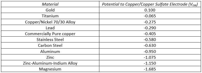
As you can see from the chart above, metals such as magnesium, zinc, and aluminum are common galvanic anodes because they generally are more negative than steel structures they are used to protect. Design criteria will dictate which of those anodes are used to protect steel, but generally speaking, a galvanic CP system will use one of those three anode materials. Galvanic systems are usually closely coupled with the structure with which they are protecting, meaning the anodes are within a few feet in distance from the protected structure. Galvanic systems only require a metallic connection to the cathode from the anode for function. While shipboard systems have zinc anodes welded or bolted directly to the hull and some short pipeline systems have magnesium anodes with leads directly thermite-welded to the outer wall, other systems have a means of “breaking” the connection between anode and cathode to be able to test efficacy. I will touch more on that in a bit.
The second kind of anode used is an impressed current anode. These anodes do not naturally conduct current when continuous in a corrosion circuit with most common cathodes. They require an external power source to “impress” current. Common anodes of this nature are mixed metal oxides on a noble metallic substrate, graphite, and high-silicon cast iron. The external power source used for operation of an impressed current system is called a rectifier. This unit is fed AC voltage, either from a nearby powerline or from mounted solar panels, uses a rectifying element (either selenium or one consisting of silicon diodes) to convert it into DC, which then polarizes the anodes to conduct current to the intended structure. Impressed current anodes have the advantage that they can be placed far away from the intended cathode, either in remote groundbeds laterally from the structure or in deep wells far below it.
Other than anode positioning, there are design criteria that will inform you whether to use galvanic or impressed current anodes in the CP system. Galvanic systems are used in low-resistivity electrolytes where current requirement is not too severe. Galvanic systems generally output 200 milliamperes maximum. It is also important that any system to be protected galvanically is electrically isolated. Shorts to other structures or the grounding system can deplete a galvanic groundbed far more quickly than the designed service life of the system.
Impressed current systems have a wide variety of uses. They are required for protecting long pipelines, larger structures, or structures that have large current demands. Structures that will be grounded or shorted to other large metallic structures will require impressed current systems. Cathodes in high-resistivity environments where galvanic systems will not be able to conduct enough current for adequate protection also require impressed current. Impressed current systems have a wide range of current outputs with some systems conducting in upwards of hundreds of amperes of current. These systems generally protect structures in seawater environments, like bridges or ship hulls.
One of the advantages of using CP is that operators and third-party contractors can easily measure the efficacy of the system using quantitative criteria set forth by AMPP. There are many standards originally set by NACE, one of the two companies that formed AMPP, governing the criteria for effective CP. Among them include SP0169-2013, which controls buried pipeline, SP0193-2016, which controls aboveground storage tank bottoms, and SP0408-2019, which controls reinforcing steel in concrete. Generally speaking, steel structures in contact with a corrosive electrolyte need to meet one of two criteria:
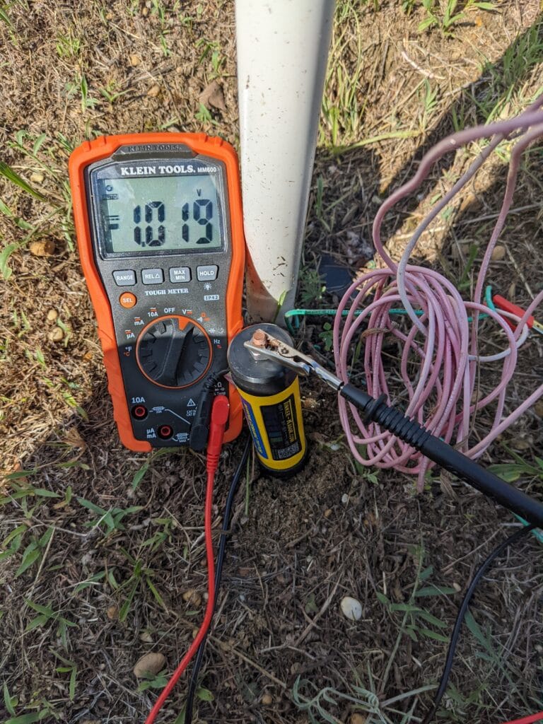
- 850 mV polarized potential measurement to a copper-copper sulfate electrode (CSE)
- Polarized potential 100 mV or more negative than the free-corroding or “native” potential, where the “polarized” potential of a structure is the potential with CP applied and no other outside voltages influencing, and the free-corroding potential is that with no CP applied at all.
Regulations for testing vary by structure and governing body. However, structures which carry hazardous material per DOT regulations must have their cathodic protection systems tested annually, with the current test date not to exceed 15 months from the last date of test. KTA-Tator offers CP testing as part of our comprehensive services to protect your infrastructure.
About the Author

Tom Holzerman is a NACE Certified Cathodic Protection Technologist for Elzly Technology Corporation (a KTA-Tator Inc. Company) with 15 years experience with corrosion control design, survey, troubleshooting, pipeline integrity inspection, and NDE testing.