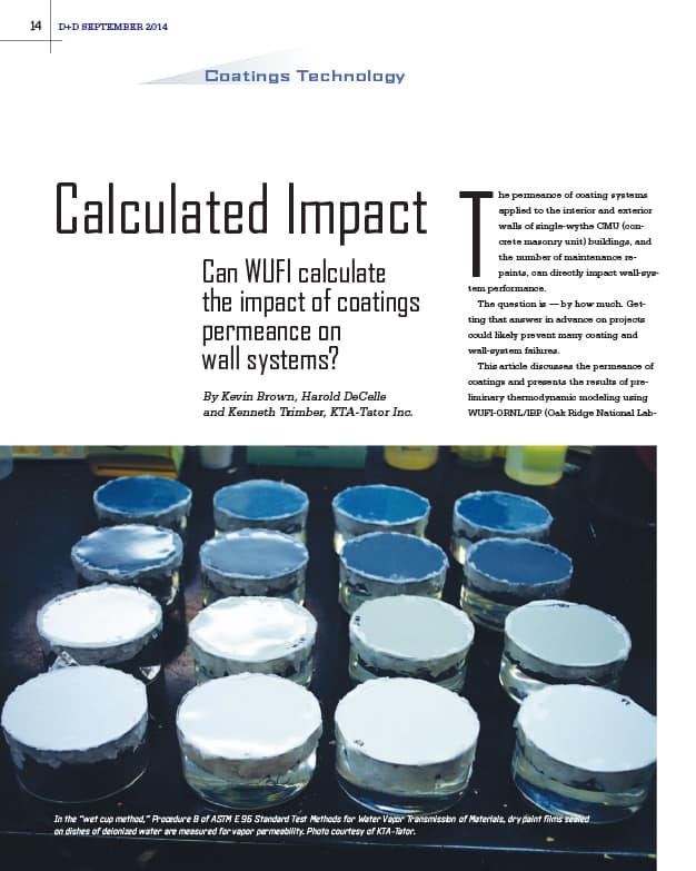
In the September 2014 issue of Durability + Design, we described the laboratory test methods used to determine the water vapor permeance of coatings, as well as the importance of knowing the permeance of the interior and exterior coatings used on building walls.
As seen in Durability & Design, January 2017
 “Calculated Impact: Can WUFI Calculate the Impact of Coatings Permeance on Wall Systems?” included the results of thermodynamic modeling of two buildings with identical wall assemblies (single-wythe CMU with open-cell foam insulation in the cavity), identical interior climates (air conditioned but without dehumidification), and the same permeance values for the coating systems. The only differences were the geographical locations of the buildings: Miami, Florida, and Providence, Rhode Island.
The modeling showed that local climate has a direct influence on the direction of vapor diffusion and liquid transport through the walls. The direction of diffusion in some cases caused excessive water retention within the wall assembly, which in turn leads to moisture-related damages.
Interior/exterior coating system combinations that did not retain water within the wall assembly in Miami retained water in Providence, increasing the potential for interior finish damage, mold growth, problems with the exterior coating (peeling, blistering), and the formation of efflorescence and lime runs on the interior and/or exterior surfaces.
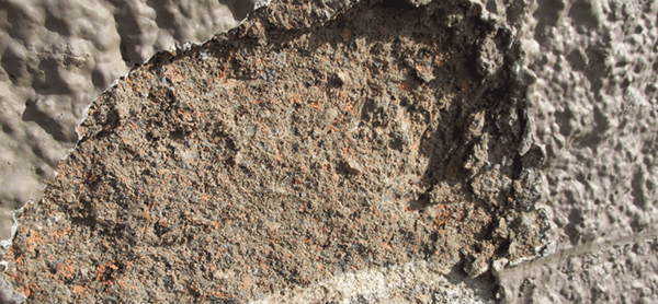
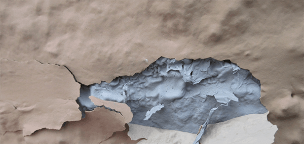
The comparison illustrates that the same paint system does not fit all geographic areas and that variations in coating permeance may be needed from one climate to another. Figures 1 and 2 illustrate the damaging effects of moisture-related problems the authors have observed.
Here, we expand on the initial research to predict how many times a single-wythe CMU building can be repainted before the reduction in permeance starts to create problems with the retention of water within the wall. For this study, four geographical locations were modelled: Miami, Florida; Providence, Rhode Island; Colorado Springs, Colorado; and Seattle, Washington.
VAPOR DRIVE
Moisture vapor in a building moves naturally from warm to cold; this is known as the thermal gradient. Vapor drive also moves water vapor from areas of high density to low density; this is known as the concentration gradient.
The greater the difference in temperature (the temperature gradient) and the greater the difference in vapor pressure (the concentration gradient), the greater is the vapor drive. When the difference between the indoor and outdoor temperatures is greater than 20 degrees Fahrenheit, the vapor drive can be quite strong.
The direction of the movement is influenced by the climate both inside and outside of the building as well as by the building design. In cold, dry climates, the vapor drive is primarily from the interior to the exterior. In warm, humid climates, the vapor drive is primarily exterior to interior.
When selecting coatings for the walls of a building, the permeance of the coating should be considered. Permeance is measured in perms and the “perm rating” is simply defined as the resistance to vapor drive. Materials are generally classified into the following categories based on permeability.
A barrier coating is typically less than 1 perm, a vapor retarder (or semi-vapor retarder) is 1 to 10 perms, and a permeable coating or “breather” is greater than 10 perms.
Some building designs and climate zones benefit from the use of exterior coatings that have very low resistance to vapor drive in order to allow moisture vapor to escape, which would be a vapor-permeable or “breathable” material. This would typically be the case in colder, drier climates where the vapor drive is from inside the building to the outside. In warmer, humid climates, an exterior coating that is a vapor retarder or that acts as a barrier may be desired in order to keep moisture vapor out, since the vapor drive is from the outside of the building inward. This would be a coating with very low permeance.
As more paint layers are applied to a surface, even if the same brand is used, the permeance is reduced with each application, and a system that starts out as permeable (breathable) can end up as a barrier (not breathable). If the optimum system to handle vapor drive requires a breathable exterior coating, the potential for retaining water within the wall increases as more coats are applied.
On the other hand, if a barrier coating is preferable on the exterior, the application of additional coats would have little to no effect on water retention.
The good news is that the risks of moisture-related wall problems based on the initial selection of the coating and number of repaints can be predicted.
MODEL DESIGN
We used WUFI-ORNL/IBP software (WUFI) for the modeling in this study. WUFI is a computer program that stands for Wärme Und Feuchte Instationär, or heat and moisture transiency.
WUFI is used to conduct hygrothermal (heat and moisture) analysis of building wall assemblies to predict when moisture problems could occur, with consideration of the interior and exterior climate of the building and the materials that make up the wall assembly.
The parameters for the wall assembly modeled in this article are single-wythe CMU measuring 7.63 inches deep, with the interior and exterior block face measuring 1.5 inches in thickness. The cavity was filled with open-cell spray polyurethane foam insulation.
ASHRAE Year 3 was selected as the exterior climate default for each city. (ASHRAE maintains a database of meteorological data [RP 1325], representing severe years for moisture damage out of a measured 10-year period. Year 3 represents the third most severe year.)
The orientation of all buildings was east, and the interior climate conditions were set at the ASHRAE 160P standard, which is a popular interior climate default for moisture-control analysis in buildings. The model assumed air conditioning with the temperature maintained between 70 degrees and 75 degrees Fahrenheit. The model simulated three years of exposure.
While WUFI does not have preprogrammed values for the permeance of coatings, experienced users can import values for coating permeance into the model. The permeance of the coating systems can be obtained from the manufacturer or through laboratory testing.
WUFI RESULTS
CMU is the primary component of the wall assembly that was modeled. CMU is a porous hygroscopic material. As such, there is a point where the pores of the material become saturated by absorption, causing unwanted moisture problems.
WUFI provides a graphical relationship between water content and relative humidity for the concrete block (brick) material housed in the program. Figure 3 shows the moisture storage function of the concrete block selected for the analysis. It shows the relationship of water content and the corresponding relative humidity.
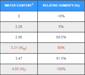
The four values in Figure 3 shown in red are significant. WUFI automatically establishes the starting point for the moisture content of concrete block in each model as 3.21 lb/ft, which is considered the “practical moisture content” for concrete block. This corresponds to an equilibrium moisture content of 80 percent RH and is designated as W. Based on our experience, 80 percent RH or less is typically an acceptable range for the performance of the wall assembly.
Moisture content of 4.05 lb/ft is considered the “free saturation point” for concrete block which corresponds to the moisture storage function at a relative humidity of 100 percent. It is designated as Wf. An RH of 100 percent is typically an undesirable condition for a wall assembly.
Note that in some porous materials, it is common to have moisture content within the supersaturation range (which is moisture content above 100 percent RH) due to the pore structure of a hygroscopic material. However, for this study, the thresholds established for the analysis are W80 (equilibrium moisture content of 80 percent, which is acceptable) and Wf (moisture storage function at 100 percent RH, which is unacceptable).
The output of each model provides the water content at the outer concrete layer (beneath the exterior coating), the interior concrete layer, the insulation layer, and the total assembly. For our analysis, only the results for the outer concrete layer are presented, but when conducting a project-specific analysis, it is important to examine the results for each of the layers as well as the total assembly. By only examining the total assembly for example, potential problems at a given layer (e.g., the outer face of the block beneath the coating) may be overlooked.
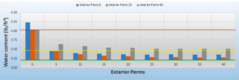
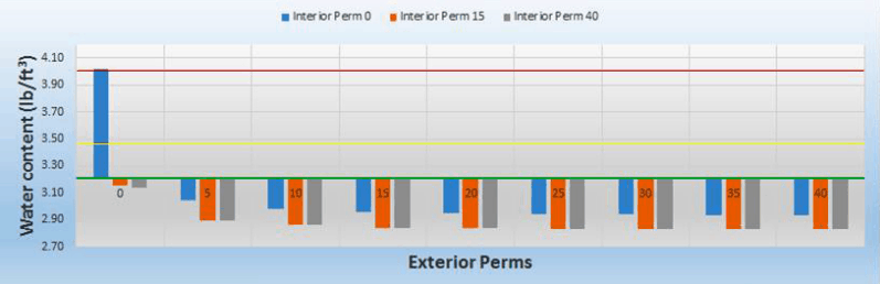
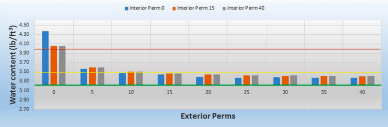
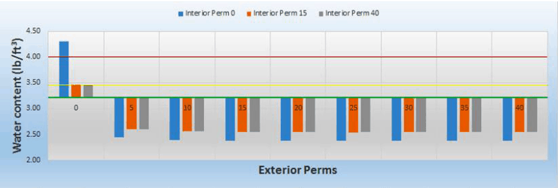
The moisture content of the outer concrete layer beneath the coating system for each of the four cities is shown in Figures 4 through 7. The x-axis shows the permeance of the exterior coating ranging from 0 (barrier) to 40 (breather) perms. There are three bars for each exterior perm that was modeled. The bars show the permeance of the coating that was modeled for the interior face of the block: 0 perms (blue), 15 perms (orange), and 40 perms (green).
The y-axis shows the water content. The W threshold is the green line. The Wf (100 percent RH) line is red. Ideally, to reduce the risk of moisture related damage, the bars should be below the green W80 line, and never above the red Wf line. The yellow line is set at 91.5 percent RH, which is a value provided in the WUFI material database for concrete brick (block).
For the modeling, it was assumed that 91.5 percent and above would create a moderate risk of having moisture-related problems based on typical concrete or masonry finishes, but we recognize some finishes will perform adequately at 91.5 percent RH and higher.
HOW MANY TIMES CAN A BUILDING BE REPAINTED?
By recognizing that the permeance of a coating system is reduced as more and more maintenance painting layers are added, it becomes clear that in certain geographical locations, the additional layers can become a problem. As the additional coating layers are added, the wall assembly starts to deviate from its original design.
To examine the effect of maintenance painting on the performance of the wall assembly, the modeling was used to determine how many times the exterior of a building can be painted before the reduction in permeance may cause problems.
The permeance for an initial coating installation, as well as after multiple repaints, was established based on past laboratory testing of the permeance of single and multiple layers of specific coating materials.
Figure 8 shows a hypothetical example of how the permeance of the coating system changes with the addition of repaint layers. Note that the permeance of the original coating system can typically be provided by the coating manufacturer, but the permeance after each repaint would need to be calculated or determined through laboratory testing.
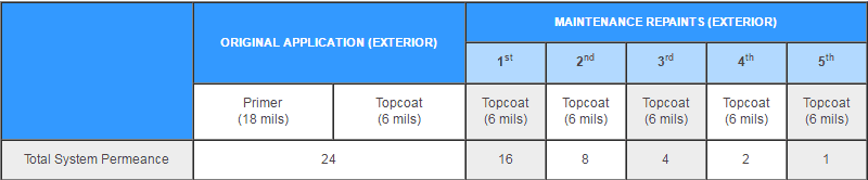
The original exterior coating installation for the example in Figure 8 consists of one block filler primer layer (18 mils) and one topcoat layer (6 mils). The permeance of the initial system is calculated at 24. This is followed by five repaints, each consisting of a single application of 6 mils each time. The permeance of the system drops after each application, ending with a permeance value of 1 after the fifth overcoat.
By using the hypothetical permeance ratings from Figure 8 and applying them to the WUFI models previously discussed in Figures 4-7, answers begin to emerge regarding how many times an exterior wall can be repainted before a risk of moisture-related problems begins to occur.
This is illustrated in Figure 9, which shows the water content within the exterior layer of the wall as the permeance decreases from multiple repaints. The data is based on an interior coating permeance of 15. Note that the results in Figure 9 will be different if different values for interior permeance are used. The risk of moisture-related problems for maintenance painting in this analysis are as follows:
- Green represents little to no risk of problems, with moisture content less than 91.5 percent RH or 3.47 lb/ft3. The performance of some coating systems may be jeopardized at a relative humidity or moisture content above this threshold.
- Yellow represents moderate risk of problems, with moisture content between 91.5 percent RH (3.47 lb/ft3) and 100 percent RH (4.05 lb/ft3).
- Red represents high risk of problems, with moisture content at or above 100 percent RH (4.05 lb/ft3).
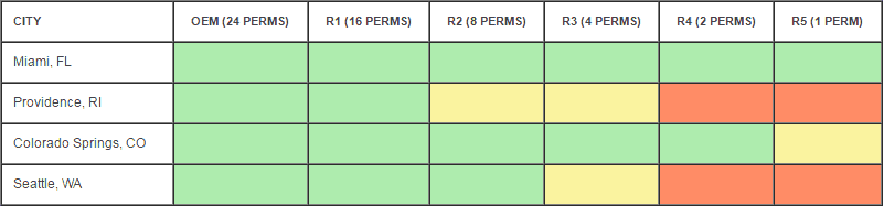
Modeling of the same building design shows that the initial application and one repaint (for a total permeance of 16) are acceptable for all four cities.
Concerns in Providence begin at the second repaint (permeance of 8), with removal of the coating likely needed at the time a fourth repaint is scheduled (permeance of 2).
Concerns with Seattle begin at the third repaint (permeance of 4) and, similar to Providence, removal of the coating will likely be needed when the fourth repaint is scheduled (permeance of 2).
In contrast, low permeance of the exterior coating does not pose moisture-related problems in Miami through all five of the repaint scenarios modeled (down to permeance of 1), and in Colorado Springs it only begins to be a concern at the fifth repaint (permeance of 1). Note that even though reduced permeance may not cause problems, the application of multiple coats after four and five repaints could still result in adhesion problems or cracking due to the thickness of the coating on the wall.
In summary, based on the variables modeled, with an interior permeance of 15, the hypothetical buildings in Providence and Seattle are best served by having as high a permeance rating as possible for the initial exterior coating and using high-permeance coatings for maintenance.
The hypothetical buildings in Colorado Springs and Miami perform well with low-permeance exterior systems, both initially and during maintenance.
POTENTIAL SAVINGS BY SELECTING THE CORRECT COATING SYSTEMS
So what does all this mean related to life-cycle cost? Based on the previous assumptions of moderate and high risks of moisture-related problems, it is deemed appropriate to remove and replace the coating when the permeance reaches high risk.
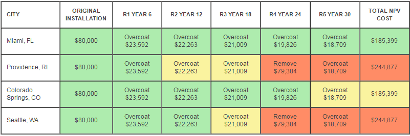
To calculate the cost impact, assume that the initial installation of an exterior coating system in today’s dollars is $80,000; overcoating is $25,000; and total removal and replacement of an existing coating is $100,000.
Figure 10 applies these costs, at net present value, to the repainting of the four buildings without making changes to the coating systems being applied during any of the maintenance cycles. For the calculations, interest was fixed at 4 percent and inflation at 3 percent. Maintenance cycles were every six years. As can be seen from this example, the financial consequences of selecting the incorrect system can be dramatically different when comparing the life-cycle cost of each building.
SUMMARY
The geographic area, seasonal changes, design of the wall type, presence/absence of insulation, interior ambient conditions, and permeance of the coating systems are some of the key factors that influence whether moisture will be retained within a wall assembly.
WUFI simulation modeling, together with knowledge of the permeance of the coating system allows building owners and architects to identify the risk of using different coating types and repainting scenarios on a building-specific basis.
The WUFI analysis, together with permeance calculations and testing, may indicate the potential for problems after one or two repaints in some climates — or no problems for five or more repaints with the same coatings in other climates.
The analysis helps answer the question regarding how many times a building can be repainted, enabling owners to influence coating design (by considering the influence of permeance), and to adequately plan for long-range capital expenditures to remove the coating layers at the correct intervals.
ABOUT THE AUTHORS

As technical director for the Commercial Services Group of KTA-Tator Inc., Kevin J. Brown develops and implements maintenance programs for commercial clients with architectural/commercial problems related to paint failures. He holds a CXLT (Certified XL Tribometrist), NACE Level 2 Coating Inspector certification, and RRO (Registered Roof Observer) certification, as well as a BS and MBA from Gardner-Webb University in Boiling Springs, North Carolina. Brown has more than 15 years of experience in the field of retail facility management, overseeing building maintenance and preventative maintenance programs for more than 1,700 stores, including store repaints, floor coating replacement, and long-range budget planning.

With more than 35 years of experience in construction and building design, Harold De Celle is a project engineer for KTA’s Commercial Services Group. He performs building envelope evaluations on commercial structures for various KTA clients nationwide and routinely performs forensic-type evaluations, which consist of destructive and non-destructive testing, on existing buildings. He is proficient in AutoCAD as well as the use of diagnostic equipment and instrumentation, such as various types of moisture meters, infrared thermography, and water spray rack equipment to assess wind-driven rain and fiber optics. Prior to joining KTA, De Celle was the vice-president/owner of De Celle Post & Beam lnc. and designed and built post and beam buildings. He holds a BS in civil engineering-structures from University of North Carolina-Charlotte. He is a member of American Society of Civil Engineers (ASCE) and the National Honor Society. He holds certification for WUFI-ORNL WUFI-PRO, Weather Analyzer, and MPI Architectural Coating Technologist (ACT) with honors.

Kenneth A. Trimber, president of KTA-Tator Inc. has more than 40 years of experience in the industrial painting field. A NACE-Certified Coatings Inspector and SSPC Protective Coatings Specialist, he holds a bachelor’s degree from Indiana University of Pennsylvania. A past president of SSPC, Trimber is chairman of the the association’s Commercial Coatings Committee, Surface Preparation Committee, and Containment Task Group, as well as a member of the Standards Review Committee. He is a past chairman of ASTM D1 on Paints and Related Coatings, Materials, and Applications and author of The Industrial Lead Paint Removal Handbook.