
When you spend money on a product or service, you expect quality, regardless of the cost. If you purchase the most inexpensive Chevrolet that is made, you still expect quality. While the braking system in the Chevrolet may be less sophisticated than a Mercedes, the brakes better work and exhibit quality commensurate with its design. You expect the parts and installation to meet all of the standards imposed by the manufacturer for that class of vehicle.
Expectations of quality for cleaning and painting commercial buildings are no different. Owners expect the paint in the can to meet the quality standards established by the manufacturer, and the installation to meet the requirements of the specification, whether it involves a sophisticated fluorourethane on a highly visible entrance awning, or a low cost acrylic on a back wall that is hidden from view.
But how is the quality of cleaning and painting determined? For many, it simply involves rubbing a hand across the surface when cleaning is finished and after the application of each coat. It isn’t clear what rubbing the surface does, but the hand cannot identify if the levels of moisture within the substrate are acceptable, or whether the ambient conditions and surface temperature are suitable, or if each coat is applied to the proper thickness. When coatings are required to resist penetration from wind-driven rain or serve as an air barrier, verification of proper workmanship at each stage of the installation is critical.
Many standards and instruments are available for verifying the quality of cleaning and painting. Not only must the appropriate instruments be selected, but they must be used properly. This article describes the operation of some of the common instrumentsused to evaluate the quality of cleaning and painting. Part 2 of this series addresses instruments and methods used for the detection of moisture.
Surface Cleanliness – Steel
SSPC: The Society for Protective Coatings (SSPC) has published standards that describe different degrees of cleaning when using hand or power tools, dry and wet abrasive blast cleaning, and water jetting. In addition to the written words, photographic guides are also available to depict the appearance of the different grades of cleaning. Some of the SSPC work was done in cooperation with NACE International (NACE).
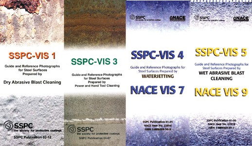
The visual guides that depict surface cleanliness are (Photo 1):
- SSPC-VIS 1, Guide and Reference Photographs for Steel Surfaces Prepared by Dry Abrasive Blast Cleaning
- SSPC-VIS 3, Guide and Reference Photographs for Steel Surfaces Prepared by Power and Hand Tool Cleaning
- SSPC-VIS 4/NACE VIS 7, Guide and Reference Photographs for Steel Surfaces Prepared by Waterjetting
- SSPC-VIS 5/NACE VIS 9, Guide and Reference Photographs for Steel Surfaces Prepared by Wet Abrasive Blast Cleaning
SSPC-VIS 3
SSPC-VIS 3 is described below as the example for using the guides. All four are used in the same manner.
Step 1 – Identify the initial condition of the steel so that the correct series of photographs is selected for the assessment of the quality of cleaning. The initial conditions in SSPC-VIS 3 are:
- Condition A – not painted – adherent mill scale
- Condition B – not painted – mill scale and rust
- Condition C – not painted – 100% rusted
- Condition D – not painted – 100% rusted with pits
- Condition E – painted – light colored paint, spots or rust over blasted steel
- Condition F – painted – zinc rich paint over blasted steel
- Condition G – painted – heavy paint over mill scale
Step 2 – Determine the degree of cleaning required by the project specification. The degrees of cleaning depicted in SSPC-VIS 3 are:
- SSPC-SP2, Hand Tool Cleaning (hand wire brush cleaning depicted)
- SSPC-SP3, Power Tool Cleaning (both power wire brush and sanding disc cleaning depicted)
- SSPC-SP15, Commercial Grade Power Tool Cleaning (needle gun/rotary peening cleaning depicted)
- SSPC-SP11, Power Tool Cleaning to Bare Metal (needle gun/rotary peening cleaning depicted)
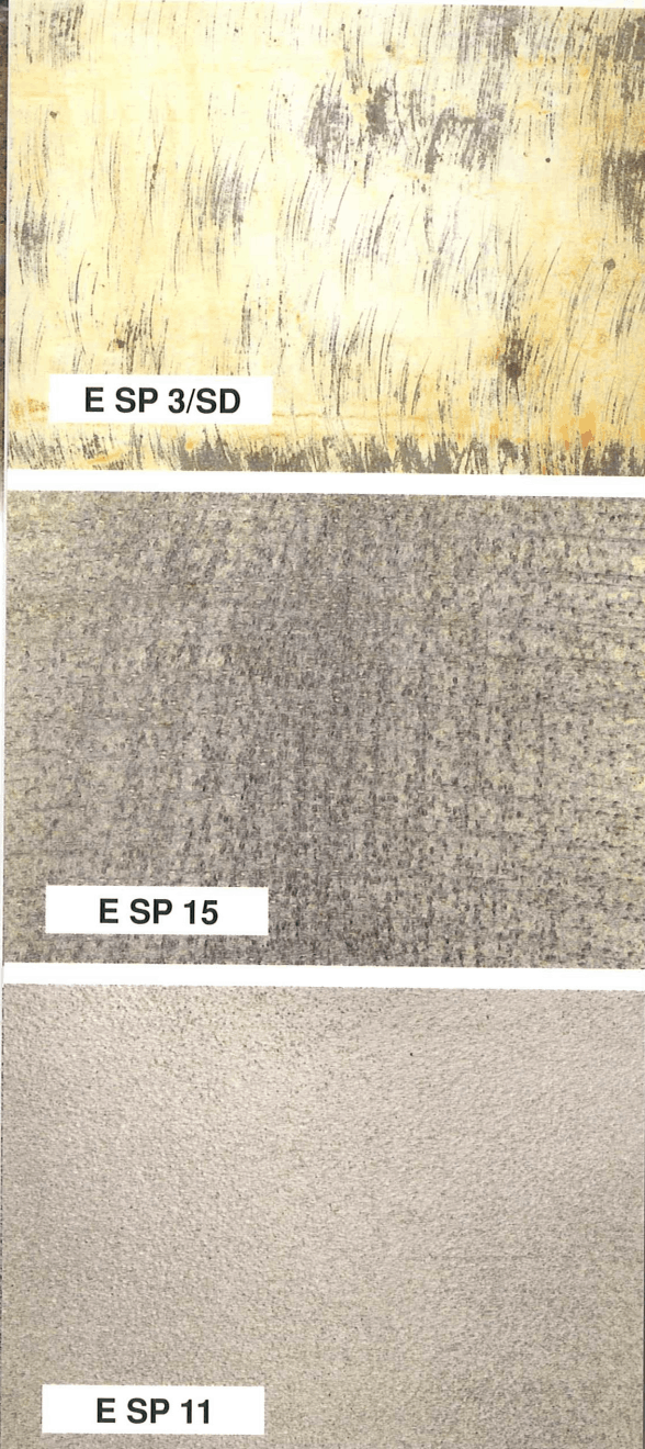
Step 3 – Locate the reference photograph for the degree of cleaning over the initial substrate condition. For example, the photograph of power tool cleaning (sanding disc) of a coating that exhibits light rust before cleaning is photo E SP3/SD (E represents the initial condition; SP3/SD represents power tool cleaning with a sanding disc). See Photo 2.
Step 4 – Compare the prepared surface with the photograph to determine if the degree of cleaning has been met.
Surface Profile – Steel
The surface profile (roughening) of the steel is commonly determined using a depth micrometer or replica tape. The methods for measuring surface profile are described in ASTM D4417, Standard Test Methods for Field Measurement of Surface Profile of Blast Cleaned Steel. Method B describes the use of a depth micrometer and Method C describes the use of replica tape.
Surface Profile Depth Micrometer (Method B of ASTM D4417)
The depth micrometer described in the ASTM standard contains spring loaded, 60° cone-shaped pin that projects from the base of the instrument. The base of the instrument rests on the peaks of the surface profile and the pin projects into the valleys. The distance that the cone projects into the valleys is displayed in 0.1 mil increments; readings can also be displayed in micrometers (µm).
Step 1 – Zero the instrument on the piece of plate glass supplied with the gage (the plate glass has been ground smooth to remove waviness), then place a horseshoe-shaped shim (also supplied with the gage) on the plate glass. Measure the thickness of the shim to verify the accuracy of the gage.
Step 2 – Hold the gage just above the probe and firmly push it against the surface to be measured. Record the reading. Readings can also be stored in memory and uploaded or printed later.
Step 3 – Pick the gage up and reposition it on the surface to take another reading. Do not drag it across the surface as dragging can blunt the tip.
Step 4 – Take a minimum of 10 readings at each test location. The maximum value of 10 readings (removing obvious outliers) represents the profile at that location.
Surface Profile Replica Tape (Method C of ASTM D4417)

The tape is used to create a replicate of the surface profile that is measured using a light spring-loaded micrometer. One instrument manufacturer has also developed an attachment for a digital gage to read the replica tape and store the results electronically. The directions below apply to the use of the spring micrometer to measure the replica tape.
Step 1 – Select the replica tape that covers the expected profile range. The tape is most accurate mid-range:
- Coarse – 0.8 to 2.5 mils
- X-Coarse – 1.5 to 4.5 mils
- X-Coarse Plus – 4.0 to 5.0 mils
Step 2 – Prepare the area to be tested by removing surface dust or contamination. This can be done by brushing.
Step 3 – Remove the paper backing from the tape. The measuring area consists of the 2.0 mil thick film of Mylar® (a polyester film) that holds a thin layer of compressible foam. The foam conforms to the depth and shape of the surface profile.
Step 4 – Attach the replica tape to the surface and burnish the back of the white Mylar circle (3/8” diameter) with a burnishing tool. See Photo 3.
Step 5 – Remove the tape and place it in the anvils of the micrometer. The surface profile is the total reading less 2.0 mils (2.0 mils is the thickness of the Mylar that holds the compressible foam). Alternatively if the micrometer is set to -2.0 mils prior to inserting the tape into the anvils, the displayed reading is a direct indication of surface profile. Two readings are taken at each location and averaged to determine the surface profile.
Note – If the surface profile measured with the Coarse tape is 1.5 to 2.5 mils, the same area must be measured with the X-Coarse tape. If that reading is also between1.5 to 2.5 mils, average the two values to determine the surface profile depth. If the second reading with the X-Coarse tape is >2.5 mils, record that value as the surface profile.
Surface Profile – Concrete (ICRI 310.2R-2013)
ICRI Guideline No. 310.2R-2013, Selecting and Specifying Concrete Surface Preparation for Sealers, Coatings, and Polymer Overlays, and Concrete Repair describes methods of surface preparation used on concrete in both written text and through the use of tactile concrete surface profile (CSP) coupons that are replicas of the type of profile (surface roughness) created by the various methods of surface preparation. While much of the standard addresses the roughness of floor surfaces, some of the methods apply to surfaces other than floors. The coupons range in texture from very smooth, typical of pressure washing (CSP1) to very rough, typical of jack-hammering (CSP 10):
- Detergent scrubbing – CSP1
- Low-pressure water cleaning – CSP1
- Grinding – CSP1-CSP2
- Acid etching – CSP1-CSP3
- Needle scaling – CSP2-CSP4
- Abrasive Blasting – CSP2-CSP7
- Shotblasting – CSP2-CSP9.
- High/ultra-high pressure water jetting – CSP3-CSP10.
- Scarifying – CSP4-CSP7
- Rotomilling – CSP6-CSP9.
- Scabbling – CSP7-CSP9.
- Handheld Concrete Breaker – CSP7-CSP10
Step 1 – Identify the method of surface preparation required by the specification or manufacturer’s requirements.
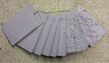
Step 2 – Select the concrete surface profile coupon(s) that represents the texture or range of textures that can be expected to be created based on the 310.2R-2013 guideline. See Photo 4.
Step 3 – Compare the prepared surface with the coupon(s) to determine if the degree of roughening is acceptable.
Ambient Conditions

For our purposes, the term “ambient conditions” encompasses air and surface temperatures, relative humidity, and the dew point temperature. See Photo 5. If the ambient conditions are outside of the limits of the specification or the coating manufacturer’s requirements, coating adhesion and film formation can be compromised, leading to reduced performance or failure. The measurements must be obtained where the work is being performed because conditions can vary at different parts of a building (e.g., in the direct sun versus the shade). The least expensive way to measure ambient conditions is through the use of a sling or whirling psychrometer and contact surface temperature thermometer. More expensive methods involve the use of digital or electronic psychrometers that contain a sensor that is exposed to the environment to determine air temperature, dew point temperature, and relative humidity. A separate probe is touched to the surface, or a non-contact infrared sensor is used to measure the surface temperature. Many different electronic models are available and the operating instructions are straight forward.
The instructions below apply to the most inexpensive method – the sling psychrometer and surface contact thermometer.
Sling Psychrometer and Surface Temperature Thermometer
Step 1 – The sling psychrometer contains two identical tube thermometers. The end of one is covered with a wick or sock (called the “wet bulb”). The other is uncovered (called the “dry bulb”). Saturate the wick of the wet bulb with clean water.
Step 2 – Whirl the instrument through the air for 20 to 30 seconds and take a reading of the wet bulb temperature.
Step 3 – Whirl the instrument again (without re-wetting) for another 20 seconds and take a reading of the wet bulb.
Step 4 – Continue whirling and reading until the wet bulb remains unchanged (or within 0.5°F) for 3 consecutive readings. Record the stabilized wet bulb temperature and the dry bulb temperature.
Step 5 – Plot the dry bulb temperature and the difference between the dry and wet bulb temperatures (delta) in the Psychrometric Tables or charts to determine the relative humidity and dew point temperature.
Step 6 – Attach a contact thermometer to the surface and allow it to stabilize for a minimum of 2 minutes to determine the surface temperature.
Step 7 – Compare the results with the specification requirements for air and surface temperature, relative humidity and the spread between the surface temperature and dew point temperature (typically the surface temperature must be at least 5°F above the dew point temperature before painting proceeds).
Wet Film Thickness (ASTM D4414)
Measurement of the wet film thickness of the coating during application provides assurance that the proper amount of coating is being applied. The coating manufacturer can stipulate the range of wet film thickness to be applied to achieve the desired dry film, or the required wet film thickness can be calculated as follows:
Wet film thickness = Specified dry film thickness ÷ Volume solids content of the paint
The volume solids content will be shown on the can label or on the product data sheet. If the solids by volume is 60% and the specified dry film thickness is 3 mils, the target wet film thickness is 5 mils (3 mils ÷ 60% = 5 mils), as 40% of the applied wet film will evaporate into the air, while 60% of the applied wet film will remain on the surface.
Wet film thickness is measured in accordance with ASTM D4414, Standard Practice for Measurement of Wet Film Thickness by Notch Gages.
Step 1 – Make sure the tips of the numbered notches (or teeth) of the wet film thickness gage are clean and free of any paint.
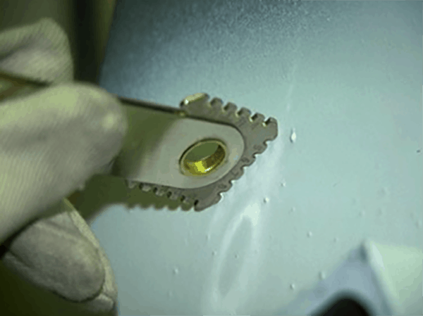
Step 2 – Immediately after the paint is applied, push the gage into the paint, making certain the end points of the gage make firm contact with the underlying surface (substrate or previously applied coating layer). See Photo 6.
Step 3 – Withdraw the gage and examine the numbered “teeth” that are wetted with paint. If none of the teeth are wetted, use a different face of the gage that displays lesser thickness. If all of the teeth are wetted, use a different face that displays greater thickness.
Step 4 – Determine the wet film thickness by looking at the numbers on the gage (in mils or micrometers). The wet film thickness is indicated by the highest wetted tooth or step.
Step 5 – Wipe all paint off the gage before it dries.
NOTE: The surface being measured has to be smooth in order to avoid irregular wetting of the teeth. For example, the gage cannot be used on split-faced block, but it could be used on the adjacent mortar joints.
Dry Film Thickness – Ferrous and Non-Ferrous Metallic Substrates (ASTM D7091 and SSPC-PA2)
There are a number of instruments available for the measurement of coating thickness on metallic substrates that are based on both electromagnetic induction and eddy current principles. The use of the instruments is covered in two standards:
- ASTM D7091, Standard Practice for Nondestructive Measurement of Dry Film Thickness of Nonmagnetic Coatings Applied to Ferrous Metals and Nonmagnetic, Nonconductive Coatings Applied to Non-Ferrous Metals
- SSPC-PA2, Procedure for Determining Conformance to Dry Coating Thickness Requirements
All of the instruments are calibrated by the gage manufacturer or an accredited calibration laboratory, but the accuracy of the instrument must be verified each time it is used, and the instrument may require an adjustment to compensate for substrate roughness. The specific instructions of the manufacturer need to be followed, but the following steps apply to all of the Type 2 (electronic) instruments:
Step 1 – Use certified coated standards in the intended range of use to verify that the instrument is operating properly (known as verification of accuracy).
Step 2 – Place a certified or measured shim (in the intended range of use) onto the prepared, uncoated metal surface and adjust the instrument (as necessary) to closely match the value indicated on the shim. This step effectively removes any influence of the base metal (metallurgy, roughness, curvature, etc.) on the coating thickness readings (Step 3).
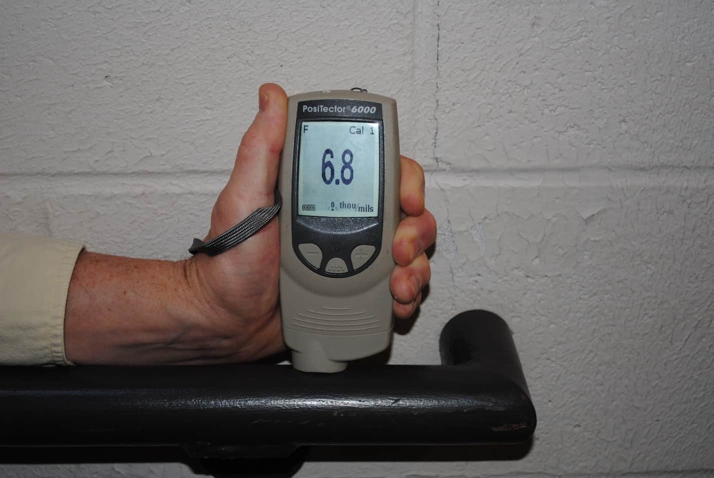
Step 3 – After verifying the accuracy of the instrument and adjusting it for substrate properties, take a minimum of 3 measurements within a 1.5” diameter circle and average them together to determine the thickness at the specific location. See Photo 7. This is known as a spot measurement. Multiple clusters of spot measurements are taken in 100 square foot areas to determine the thickness of the applied coating.
NOTE: When measuring the thickness of a coating over existing paint or galvanize, the thickness of the existing paint or galvanize must be measured and subtracted from the total reading (i.e., the gages measure the cumulative thickness of all coats that are present on the substrate). One instrument manufacturer provides a gage that will measure the cumulative thickness of the galvanize-coating layers, then display the thickness of each layer separately.
Dry Film Thickness – Cementitious Substrates, Plaster, and Drywall (ASTM D6132 and SSPC-PA 9)
The dry film thickness of coatings applied to cementitious substrates is often estimated by measuring the wet film thickness at the time of application, calculating coverage rates, using a Tooke Gage (destructive in-situ technique described later) or removing chips of the dry coating for microscopic measurement of cross-sections. If a sample of the coating can be removed with none of the substrate attached (although being able to remove such a sample could be an indication of problems), a micrometer can be used. There is also one relatively new technique available for the non-destructive measurement of dry film thickness. It involves a special instrument that measures thickness using ultrasound principles. See Photo 8. The technique is addressed in ASTM D 6132, Standard Test Method for Nondestructive Measurement of Dry Film Thickness of Applied Organic Coatings Using an Ultrasonic Gage; the frequency of measurement and the acceptability of the measurements is addressed in SSPC-PA 9, Measurement of Dry Coating Thickness on Cementitious Substrates Using Ultrasonic Gages.

The specific methods for using the instrument should be followed according to the manufacturer’s instructions, but the following basic steps apply:
Step 1 – Allow the probe to reach ambient temperature in the same environment where the readings will be taken by holding the probe in the air and pressing “zero” in the main menu. This helps the gage to compensate for temperature extremes and the effects of wear on the probe.
Step 2 – Verify the accuracy of the gage using known reference standards. For polymer coatings, place a plastic shim (reference standard) on the bare substrate, apply a drop of couplant on the surface of the shim, and place the probe on shim through the couplant to measure the thickness of the shim. The couplant carries the ultrasound signal from the probe to the coated surface (the shim in this case). Adjust the gage to register the thickness of the shim.
Step 3 – Set the “gates,” which are the minimum and maximum range of thickness expected to be measured.
Step 4 – To measure the thickness of the coating, apply a drop of couplant to the surface of the coating and firmly place the probe on the coating through the couplant. A second reading in the same area can be taken without reapplying the couplant. But when moving to a new location, couplant must be reapplied to take a reading.
Dry Film Thickness (Destructive) – Any Substrate (ASTM D4138)
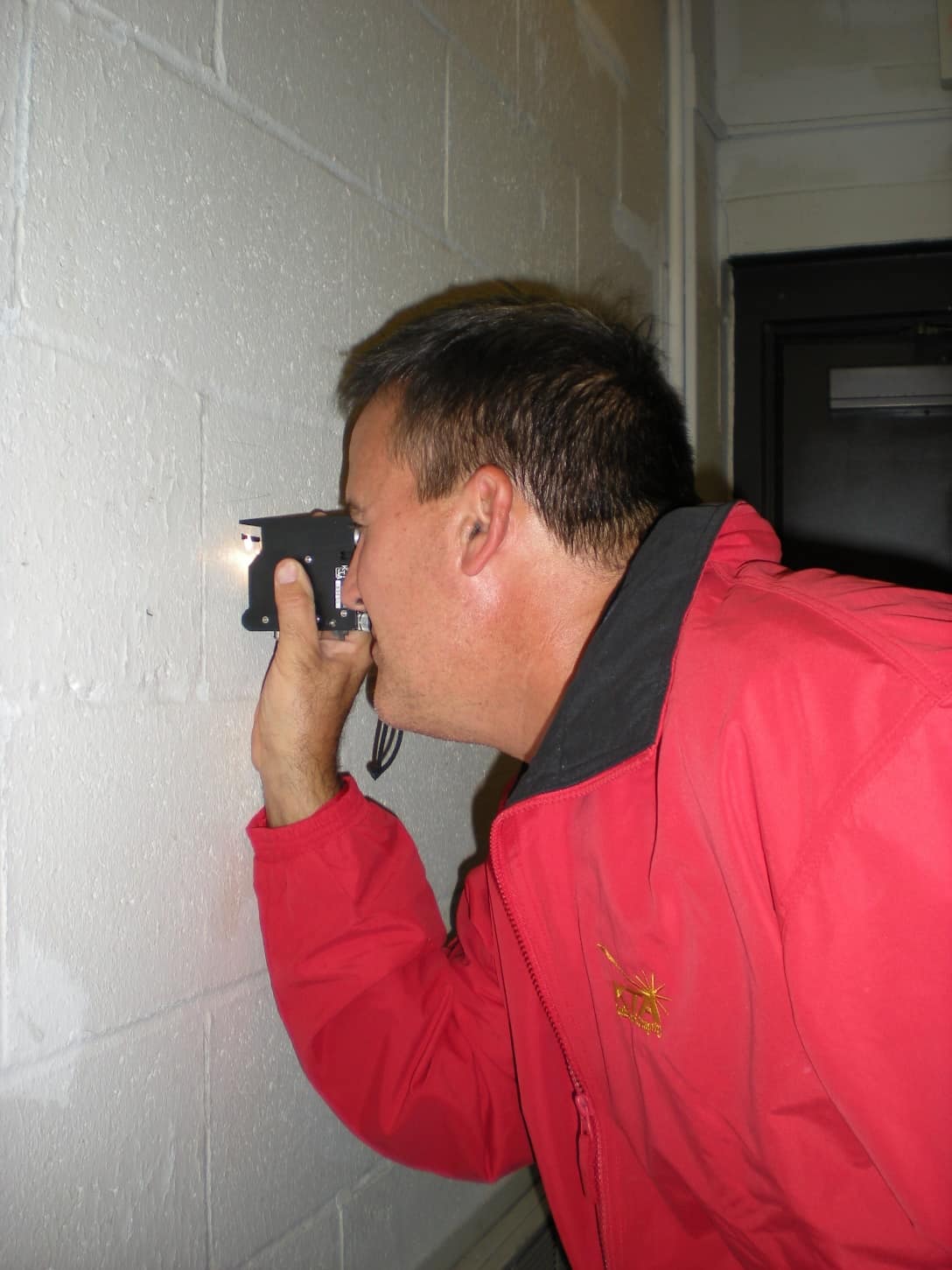
The Tooke Gage is a destructive microscope technique (50x ocular) for the measurement of coatings applied to essentially any substrate (all metals, cementitious substrates, wood, plaster, drywall, plastics). See Photo 9.
The Tooke Gage is used in accordance with ASTM D4138, Standard Practices for Measurement of Dry Film Thickness of Protective Coating Systems by Destructive, Cross Sectioning Means. In addition to total thickness, the Tooke Gage allows for the measurement of the thickness of each coat in multi-coat systems. The gage requires the use of special cutting tips to make a precision incision through the coating layers(s) at a known angle and the thickness is determined using basic trigonometry. By measuring the width of the scribe, the depth or thickness of the coating can be determined because the angle of the cut is known. However, knowledge of mathematics is not required to use the instrument. All of the conversions are established by the instrument.
Step 1 – Select the cutting tip that is in the range of coating thickness to be measured. Three cutting tips are available. The differences between them are the cutting angle provided by the tip:
- 10x tip – for thickness <3mils
- 2x tip – 3 to 20 mils
- 1x tip – 20 to 50 mils
Step 2 – Create a benchmark on the coating using a marker. Use the selected cutting tip to make an incision approximately 1” in length through the coating in the area of the benchmark. The instrument requires 3-point contact when making the cut (two legs and the cutting tip). Pull the cutting tip toward you to make an incision with the legs leading the tip.
NOTE: For the readings to be accurate, the incision must be made perpendicular to the surface. Because of this, the area being measured must be smooth. If the surface is irregular, the cutting angle will not be consistent and the results invalid.
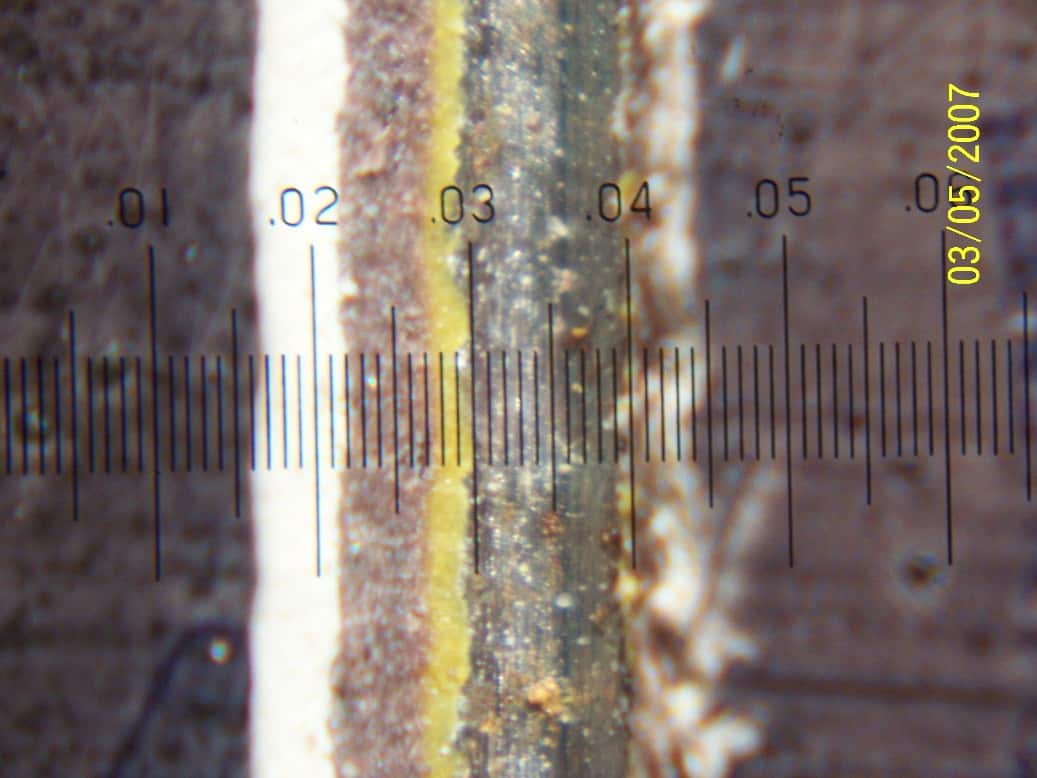
Step 3 – View the incision through the 50x ocular with the reticule perpendicular to the incision. See Photo 10.
Step 4 – Count the number of divisions of the reticule that line up with each coat to be measured. The correlation between the number of divisions and thickness depends on the model of microscope supplied with the gage because 2 different oculars with reticules have been available. Verify the conversion with the instructions supplied with the instrument, but it will be one of the following:
| Microscope A
(typically purchased before 2011) |
Microscope B (Universal ocular)
(typically purchased after 2011) |
|
| 1x Tip | 1 division = 1 mil | 1 division = 2 mil |
| 2x Tip | 1 division = 0.5 mil | 1 division = 1 mil |
| 10x Tip | 1 division = 0.1 mil | 1 division = 0.2 mil |
Conclusion
There are a variety of standards and instruments available for verifying the quality of cleaning and painting. The tests are easy to conduct, but specific steps are required to make certain that the instruments are used properly and that the results are valid. A few tests and inspections during the work can make the difference between successful coating performance and premature coating failure.
See part 2 in this Series for a discussion of instruments and methods used for the detection of moisture in cementitious substrates.
ABOUT THE AUTHOR

Hi.
Do you have any tools and techniques to measuring moisture on mdf covered with polyurethan precoat and final coat?
Thank you for your answer.
BR
Tomislav
Tomislav,
Moisture is covered in the 2nd part of this article. Click here: https://ktauniversity.com/tools-and-techniques-for-measuring-coating-quality-part-2/
Hope this helps!
Please tell me if there is equipment out there to measure cleanliness of surface before Coating/Epoxy. If there is, please let me know the name of manufacturer, as well as model.
Moe, I’ve forwarded your request to our Instrument Sales Manager, Matthew Fajt (mfajt@kta.com) – he should be able to answer your question & point you in the right direction. Thanks for your inquiry!
Is there a way to determine the hardness or scratch resistance of coatings on a concrete floor?
With kind regards
Peter
Peter, thanks for your question! The following is a response from the author, Ken Trimber:
If the coating is somewhat heavy you could use a Barcol Hardness Tester or Shore Durometer. However, if it’s thin like a sealer, you need to be careful because you could penetrate the coating and be unknowingly measuring the concrete itself rather than the coating. Although not specifically asked, if you run into bare concrete (e.g., polished concrete) you can use Mohs hardness. There’s also a lab test for mar and scratch resistance of coatings. It’s ASTM 2197, Standard Test Method for Adhesion of Organic Coatings by Scrape Adhesion. Despite the title, it will also provide an assessment of scratch and mar resistance. Regards, Ken
can replica tape be used to measure a needle gunned surface profile
Keith, the following is a reply from the author, Ken Trimber:
You will get a reading, but both SSPC-SP11 and SP15 state that the profile of power tool cleaned is to be measured with the depth micrometer (Method B of ASTM D4417), although the footnote attached to the paragraph appears to leave the door open for testing both the tools and profile instruments on a job-specific basis for suitabiity. The text below is from SP11 .
2.4 The profile shall be measured in accordance with ASTM D 4417 Method B unless otherwise specified (see Notes 8.4, 8.5, and 8.6).1
1 Although ASTM D 4417 and ASTM D 7127 indicate in their titles that they describe methods intended for use on blast-cleaned steel, there is currently no method specifically designed for measurement of profile on steel surfaces prepared using power-tools. Visual comparators used for ASTM D 4417 Method A represent surfaces prepared by abrasive blast cleaning and are inappropriate for comparison with power-tool cleaned surfaces. The replica tape used for ASTM D 4417 Method C cannot accurately measure the profile produced by some types of power-tool cleaning media. A test area prepared at the job site can be used to assess the suitability of media and profile measurement method for a project prior to full-scale production.
Thank you for all the good information you have been writing,please keep it up, more grease to your elbow.Coating business is a continuous education. It will boost inspector’s competency.
Thanks for your comment and we agree that the coatings business requires continuous education. Each of us should embrace learning as an integral part of our jobs.
nice content.