This month’s case from the F-Files concerns the application of a high performance liner in a steel demineralized water storage tank, or a demin tank. Demineralized (purified) water can be particularly aggressive in service when even minute traces of soluble salt contamination are present on a coated substrate. Therefore is not uncommon to see soluble salt remediation and high degrees of surface cleanliness (e.g., SSPC-SP 5, White Metal Blast Cleaning) prior to lining installation. The liners are normally chosen based on superior chemical and water immersion resistance.
In this case the application of a liner to the interior of a demineralized water storage tank was halted mid-way through the process due to evidence of dramatic defects in applied film. The general contractor arranged to have an independent evaluation conducted to assess the suitability of the liner material for service and an explanation of why it exhibited runs, sags, fingering and “sliding” separation during installation.
Background
The general contractor received bids from steel tank fabricators to supply and erect several storage tanks including the demin tank. The successful tank fabricator was also responsible for installation of the tank linings. A technical specification for preparation and lining the demin tank was issued as a contract addendum. The addendum identified an acceptable liner manufacturer and product for the demineralized water tank, but also permitted substitution of an “or equal” product for consideration. The fabricator selected an experienced industrial coating firm as the subcontractor to install the liner.
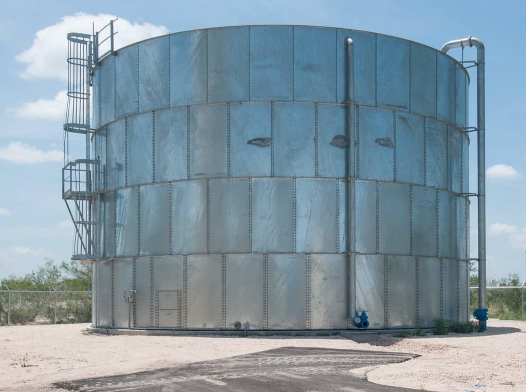
The demin tank was approximately 30 feet in diameter and 42 feet high at the top of the shell wall. The tank roof was a dome design without interior structural supporting columns. Once in service the tank would supply demineralized feed water at temperatures of up to 130oF to a newly constructed boiler. The integrity of the liner was known to be critical to facility operations. A peeling or delamination failure of the liner could lead to blockage of water flow and create significant boiler operational difficulties. The general contractor recognized that an improperly installed liner would represent a significant liability to all of the parties involved. Therefore, at the discovery of application difficulties an independent assessment was conducted.
Liner Material
The liner was an amine cured 100% solids epoxy. The product data sheet (PDS) recommended a material storage temperature of 50-85oF but also recommended raising the material temperature a day or two before application, if necessary, to optimize the material for mixing and spraying at 70-85oF. The mixing instructions called for Component A (resin) to be stirred for two minutes and Component B (pigmented hardener) mixed separately to achieve a uniform color. Part A and Part B may then be mixed together (4:1 by volume) for application by airless spray. Alternatively, application could be performed using plural component airless spray with fixed ratio (4:1) material pumps. The plural component material lines would require heating to a prescribed temperature range to maintain proper volume proportioning. The product pot life was 45 to 60 minutes at 75oF[1]. No thinner was recommended. Prior to application, all substrate surface defects were to be corrected, the surface verified as meeting the required degree of surface cleanliness, and corners, edges and welds to be stripe coated by brush “scrubbing”
The specification called for the liner to be applied at 40 mils dry film thickness (DFT) in one or two coats. The coating manufacturer’s data sheet indicated the product is typically applied from 20 to 40 mils thick in a single coat and cautioned against exceeding 60 mils.
Surface Preparation
The specification required that the prepared surface of the steel substrate meet the cleanliness of SSPC-SP 10, Near White Blast Cleaning, which was consistent with the coating manufacturer’s requirements. The coating manufacturer called for steel surface defects (gouges, weld spatter, rough welds, dirt, contaminants, etc.) to be corrected prior to abrasive blast cleaning, and that the abrasive blast cleaning produce a dense, sharp angular profile of 3 to 4 mils. The roof plates were blast cleaned and coated at the painting contractor’s yard[2] and shipped to the job site along with the shell plates which were not prepared or coated prior to delivery. The roof weld seams and the entirety of the tank interior shell walls and floor were to be abrasive blast cleaned to a near-white condition (SSPC-SP 10) following erection.
Project Execution
Records from the coating application shop operations indicated the interior of the roof plates and interior roof I-beams were blast cleaned and coated during mid August. The anchor profile from blast cleaning was reported to range from 3.0 to 3.6 mils in depth and the applied coating ranged from 37 to 43 mils in thickness. The next set of coating related records were dated mid-October, indicating that the demin tank erection was complete since surface preparation and coating application on the interior had begun.
Inspection and work progress records were incomplete and provided limited information regarding the surface preparation and coating application details. However the records indicated anchor profiles of 5.5 to 6 mils were measured (with X-Coarse replica tape[3]) and that when some portions of the blast cleaned steel were found to meet the specified cleanliness requirement they were coated to avoid “losing the blast.” However, a series of equipment and application problems occurred and project progress was poor.
It was reported that 5% thinning with methyl ethyl ketone (MEK) was performed for application purposes. The MEK was obtained from a vendor other than the coating manufacturer. The MEK was added to component B, the product allowed to stand to release heat (exotherm) then mixed once the temperature stabilized. It should be noted that only two material temperatures were documented in the field inspection reports provided for review, one indicating a low material temperature (55oF) and the second a high material temperature (90oF).
The general contractor halted further work in the demin tank until the on-going difficulties could be addressed and corrected. Coating manufacturer representatives worked to identify the application problems and prepared recommendations for repair or replacement of the liner. The general contractor elected to have a third party investigate the problems as well.
Field Investigation
A visual examination of the tank interior revealed that the lower shell wall and floor were not prepared or coated. The floor was covered with spent abrasive and the bottom shell ring had thick runs of coating, as much as six feet long, originating from the shell ring above. Examples are shown in Figure 1 and Figure 2.

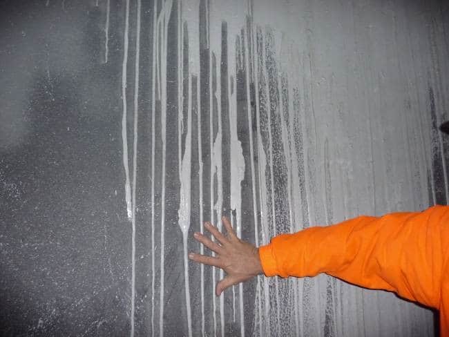
The coating above the first ring, in addition to having long runs, contained thick and wrinkled sags. Very thick accumulations of coating film also resulted from the bulk of the partially gelled coating film literally sliding down the tank wall leaving a thin, translucent coating film behind as shown in Figures 3 and Figure 4.


The thin coating film did not have visible voids, discontinuities, bubbles or pinholes at the surface. The film texture was generally smooth except when the bulk of coating stopped sliding and the material above backed up causing heavy wrinkles. Apart from the areas of sags and runs there were locations of prior applications where the applied film looked smooth and uniform and other applications where the coating film had a heavy orange peel texture and still other locations where numerous pimples were present in the film. The pimples could be easily removed with a scraper but when they were removed many revealed voids or pinholes in the coating. Figure 5 and Figure 6 provide examples.


Dry film thickness (DFT) was measured using a Type 2 (electronic) film thickness gage. As surmised from the visual examination, the applied coating was well outside of the typical 30 to 40 mil thickness range recommended in the manufacturer’s product data sheet. The DFT of the tank roof plates that had been prepared and coated at the shop ranged from 57 to more than 60 mils[4]. The coating film thickness on field blast cleaned and coated roof plate spots and weld seams ranged from 9 mils up to 25 mils. Data are provided in Table 1 below.
Table 1- Roof Plate Liner Thickness
|
Roof Plate |
Dry Film Thickness, Mils |
| Plate surface |
57 to >60 (77) |
| Weld seam |
18 to 25 |
| Spot Blast |
9 to 10 |
| Circumference |
10 to 13.5 |
The coating on the shell wall exhibited even greater variations in coating thickness. The thin films left behind when the coating slid down the shell wall were between 2.5 and 6.8 mils thick with an average of about 4 mils. The thick edges of curtains were over 1/8 inch (125 mils). Typical thicknesses were 20 to 3l mils where smooth uniform films were present.
Coating adhesion could not be assessed by ASTM D 3359, “Measuring Adhesion by Tape Test” or ASTM D 6677, “Standard Test Method for Evaluating Adhesion by Knife” since both methods require scribing through the coating with a sharp blade to the substrate (the liner was too hard to scribe through to the substrate). A wood chisel and hammer was used to remove coating from the surface. Pimples and tops of coating runs could be removed from the surface of the liner by scraping and chipping. It was necessary to hammer the back of the chisel to remove the liner to the substrate. Even then it was very difficult to remove more than small chips.
The bottom shell ring, as noted above was not yet prepared for lining application. Runs on the surface were forced off with a chisel and found to contain black mill scale on the back surface. Liner chips removed from surfaces that were blast cleaned appeared free of mill scale and debris.
The painting sub-contractor blast cleaned an area of approximately 240 ft2 to assess the effort required to remove the applied liner. The surface profile was measured and exceeded 4.5 mils[5]. The cleanliness was judged to be consistent with the requirements of SSPC-SP 10, Near White Blast Cleaning except for some small locations where coating remained in the profile.
Three samples were removed from the tank liner and submitted for laboratory examination. These are identified below.
Samples from the Demineralized Water Tank Liner
|
Sample Identification |
Description and Location |
|
Sample 1 |
Heavy Run, Bottom Shell Ring Wall |
|
Sample 2 |
Coating Pimples on Shell Ring 1 |
|
Sample 3 |
Heavy Run, Shell Ring 2 Wall |
Laboratory Investigation
The samples were examined by infrared spectroscopy (FTIR) to identify (confirm) resin type and compare the samples for similarity in formulation and mix ratio. The coating samples were confirmed to be epoxy and there was no indication of mix ratio differences. Microscopic examination revealed voids in the films and the back surface of Sample 1 to have a black layer, presumably mill scale layer about 1 mil thick. Rust spots were also noted. The thickness was about 40 mils. Sample three, applied to blast cleaned steel did not have a black layer or rust spots on the back. The sample examined was 60 to 66 mils thick. Figure 7 shows the back surface of Sample 1 and Figure 8 shows the back surface of Sample 3.


Conclusion and Recommendations for Repair/Replacement
The runs, sags, curtains and “sliding” of the liner in the demin tank were the direct resulted of improper storage, handling and application of the product. The materials were not always stored at the recommended temperature range and were applied at material temperatures outside of the recommended mixing and application temperature ranges.
The contractor elected to apply the lining using traditional airless spray equipment, appropriate per the product data sheet, but had equipment difficulties. The lining was applied below the recommended application temperature. In an effort to avoid repeating this error the direct application of heat to the coating containers to warm the contents was attempted. However the temperature increase was too fast and too high causing product to stick to the containers and quite likely resulted in application beyond the pot life of the product. The use of thinner, not recommended by the manufacturer, caused additional problems. Thinner addition is typically done to aid in spray properties and may be called for to control the release of solvents under different environmental temperatures. However, the use of thinner in this instance was a poor decision. First, spray properties are influenced by material temperature. Thus the coating temperature should be in proper range prior to deciding if thinning is necessary. Second, in this instance the addition of MEK to Part B resulted in an exotherm- sufficiently great to postpone mixing until the temperature “stabilized.” There are numerous implications associated with this condition; including pot life, solvent release, and viscosity changes, perhaps due to a rapid exotherm and gelling which would account for the runs, sags and sliding characteristics associated with the last application.
The records, while incomplete documented instances of equipment failure and improper mixed material temperatures. However, failure to maintain more complete quality control records; ambient conditions, surface temperature, mix times, material temperature, product thinning and pot life, etc. made problem resolution haphazard. This appeared to demonstrate that the field crew involved in the application of the liner was complacent in their work when in reality they lacked experience in the application of the product and the critical nature of the material temperature and properties.
DFT values reported in the records from the application of the coating at the blast yard indicate that the roof plates received the specified thickness. Measurements in the field would support this only if the additional coat applied in the field were considered part of the measured total DFT.
An option posed by one manufacturer to address the failed liner in the demin tank included one of several alternative epoxy products to tie to the salvageable applied liner. These same products could be applied as a multi-coat (thinner) liner for the interior steel surface yet to be coated. Although the alternative products were suitable for immersion service, there remained the issue of the surface preparation process that had already generated surface profiles in excess of the recommended depth for the proposed alternative epoxies. Further, test removal of the failed liner generated deep anchor profiles as well. Although the manufacturer reported that such repairs had been successfully used in the past, the general contractor was not interested in a hybrid system without a thorough study.
The coating manufacturer also presented a remediation option of removing severe sags, sweep blasting the remaining installed liner and applying a fresh coat of the same liner material to achieve the specified DFT. Although the specifics of the repair procedure were not available for review, this approach appeared to be the most reasonable option for salvaging portions of the applied liner. If this approach was to be undertaken, it was recommended that narrow guidelines be established for accepting portions of the installed system. The options for repair and for removal and replacement are described below.
Option 1- Repair and Recoat
It was recommended that repair procedures include the following steps.
Store all coating materials in strict accordance with the manufacturer’s instructions.
The roof plate lining does not need to be removed. However, holiday testing should be performed and any discontinuities corrected. Apply additional coating to surfaces adjacent to weld seems, spot blast clean areas and surfaces along the circumference of the roof that do not have the minimum specified DFT recommended by the manufacturer. This should be performed in accordance with the manufacturer’s application specification. Note: A caulk or sealant recommended by the manufacturer should be installed in the seam between the shell wall and roof plates.
Wash the applied liner (including roof plates) with soap and water to remove any amine exudates (blush) that may have formed on the surface. Thoroughly rinse the surface to remove soap residue and allow drying.
Remove all runs, sags, slides and defective coating by grinding, power sanding and abrasive blast cleaning. Thin films present due to sliding of the film, or applied at less than 15 mils are to be fully removed. Runs and sags that extend beyond an underlying intact film are to be fully removed.
Liner films that overlap onto surfaces that were not inspected and verified as properly prepared are to be fully removed.
Lightly abrade remaining sound coating by sweep blast. (Note that adjacent exposed steel will require blast cleaning to the specified degree of cleanliness.)
Remove dust and residues from interior surfaces by vacuuming.
Perform low voltage holiday testing on coated surfaces with a DFT of 20 mils or less.
Perform high-voltage[6] testing on coated surfaces with a DFT of greater than 20 mils.
Repair all discontinuities as recommended by the manufacturer. Multiple discontinuities within 1 square foot will be cause to remove the coating in that area at the sole discretion of the general contractor.
Mix and apply the originally approved liner product in strict accordance with the manufacturer’s PDS and published Application Specification. Plural component application is recommended.
Option 2- Remove and Replace
Full removal of the existing liner should be completed prior to beginning installation of the replacement liner except that the roof plate lining need not be removed. However, holiday testing should be performed and any discontinuities corrected. Apply additional coating to surfaces adjacent to weld seems, spot blast cleaned areas and surfaces along the circumference of the roof that do not have the minimum specified DFT recommended by the manufacturer. This should be performed in accordance with the application specification. Note: A caulk or sealant recommended by the coating manufacturer should be installed in the seam between the shell wall and roof plates.
Install the liner in strict accordance with the manufacturer’s PDS and application specification. Prepare a Quality Control Plan for all phases of the work and provide a trained Quality Control Inspector and fully complete the daily inspection forms. Document on the inspection forms any notification to the foreman or superintendent of observations, tests or measurements that are outside of the specification.
Provide safe access and allow time for the general contractor’s Quality Assurance Inspections. Hold point inspections to permit the Quality Assurance Inspections will be established by the general contractor.
Perform high voltage holiday testing on the installed liner. Repair discontinuities and retest the repaired areas.


