
KTA’s Certified Coating Inspector Forum
Volume 4, Issue No. 6 – July 2025
William Corbett, Technical Consultant and KTA Fellow
AMPP Senior Certified Coating Inspector & Certified Protective Coating Specialist
KTA’s Certified Coating Inspector Forum is designed to provide professional development/continuing education on standards, inspection practices, new instruments, and other topics to help keep certified AMPP and FROSIO coating inspectors current. It represents the views of the author and KTA-Tator, Inc. It may or may not represent the views of AMPP: The Association for Materials Protection & Performance, even though SSPC, NACE, and AMPP standards are frequently referenced in the content.
Introduction
Concrete is frequently coated to isolate it from service environments that may cause deterioration, for decontaminability, or to improve aesthetics. Similar to metallic substrates, the thickness of the applied coating can be measured in both the wet and dry state. However, the principle of non-destructive measurement of coatings on concrete in the dry state is very different than non-destructive measurement of coatings on metal substrates.
This issue of the KTA Certified Coating Inspector Forum describes non-destructive thickness measurement of coatings applied to concrete, as well as the procedure for determining conformance to the specified dry coating thickness requirements (i.e., frequency and acceptability of measurements) described in industry standards.
Industry Standards
There are two industry standards that are focused on the measurement of coating thickness on non-metallic substrates, such as concrete, using nondestructive methods:
- ASTM D6132, Standard Test Method for Nondestructive Measurement of Dry Film Thickness of Applied Organic Coatings Using an Ultrasonic Coating Thickness Gage
- AMPP SSPC-PA 9, Measurement of Dry Coating Thickness Using Ultrasonic Gages
ASTM D6132 focuses primarily on gage use, while AMPP SSPC-PA 9 focuses on frequency and acceptability of measurements obtained according to ASTM D6132. That is, these standards are not competing but rather complementary and designed to be used in conjunction with one another. Note that the gages described in this article can also be used to measure coating thickness on wood, plastic, and other non-metallic surfaces, however these applications are not described.
Measurement Principle
Defelsko Corporation
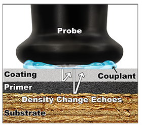
The common instruments used for the non-destructive measurement of coating thickness on metallic substrates are based on magnetic induction or eddy current principles, but they will not work on concrete. For the measurement of coating thickness on concrete, instruments based on ultrasound are used. A few drops of couplant or gel (required) are applied to the coated surface where the measurement will be taken. A non-destructive coating thickness gage equipped with an ultrasonic probe is placed on the coated surface through the gel to obtain a measurement. Water is an ideal couplant for coatings on a smooth, horizontal surface. For coatings on a rough surface (or for measurement on vertical surfaces), a propylene glycol gel is best, provided it is compatible with (does not attack) the coating to be measured. Most gage manufacturers supply a gel with the gage probe. Note that all couplant should be removed from the surface once the measuring process is complete, which may include wet wiping with water.
When the probe contacts the coated surface, an ultrasonic signal (sound vibration) penetrates the coating film (via the couplant) at a given velocity until the vibration reflects off a dissimilar surface (e.g., the concrete/coating interface, since these will have different densities) and returns to the probe (i.e., “echoes”). The total signal (sent and received) is automatically divided by 2 and displayed as coating thickness in mils, millimeters, or micrometers. Coating thickness up to 300 mils (7.5 mm) can be measured.

Defelsko Corporation
Coating layer interfaces (having different densities), air voids in the coating (or air-entrained coatings), highly filled coatings such as mortars, or flake-like pigmentation (e.g., glass flake) in a coating can cause false, low values. The ultrasound signal senses that these interfaces have different densities and bounces back to the probe before it reaches the coating/concrete interface. If you encounter this issue, you may have to rely on wet film thickness, calculations of coverage rates, or destructive microscopic testing (Tooke Gage, Paint Inspection Gage, or removal of samples for laboratory measurement).
Calibration, Verification of Accuracy, and Adjustment
The processes (steps) for Calibration, Verification of Accuracy, and Adjustment are somewhat different than those used for magnetic induction or eddy current gages.
Step 1: Calibration is performed by the gage manufacturer or an accredited calibration laboratory using standards that are traceable to a national metrological institution (e.g., NIST, National Institute of Standards and Technology). Annual calibration is typically recommended by gage manufacturers, and the Certificate of Calibration issued by the calibration lab should be filed, and a copy maintained with the gage. Frequently a calibration “due date sticker” is attached to the gage or probe to indicate when it is due for recalibration. A calibration lab accredited to ISO/IEC 17025 can be used, provided this type of measuring instrument is listed on their scope of accreditation.
Step 2: Verification of Accuracy is performed by the gage operator prior to and after each period of use using traceable, certified, standards. For ultrasonic coating thickness gages, these standards are frequently a set of four polystyrene blocks (purchased separately) ranging in thickness from 15-125 mils that can be placed on any smooth surface that is dissimilar to the polystyrene. Use of the couplant is required when performing this step.
Step 3: Adjustment. According to ASTM D6132, measurement accuracy directly corresponds to the velocity that sound moves through the coating being measured. Because ultrasonic instruments measure the total transit time of an ultrasonic pulse, they may require an adjustment by the user for the type of coating material to be measured. To determine if an adjustment is necessary, the actual thickness of the coating must be determined using a destructive, cross-sectioning method (ASTM D4138[1]), removing and measuring the coating with a micrometer, or cross sectioning and measuring the thickness of the coating cross-section under a microscope or by computerized image analysis. Obviously “Adjustment” using the latter method must be performed in a laboratory. If the thickness of the coating (using one of these methods) is different than the non-destructive thickness measurement obtained with the ultrasonic gage, then an adjustment to the gage is appropriate. The gage manufacturer provides instructions for proper gage adjustment. This “Adjustment” step makes measurement acquisition of coatings on concrete much more challenging.
While not part of the ASTM D6132 standard, control samples of the coating (i.e., drawn downs of the coating at various thicknesses) could be applied to a non-stick surface such as Mylar®, then removed after drying, measured using a micrometer to determine the actual thickness, then used during the adjustment process.
Measuring Coating Thickness

Defelsko Corporation
Once the steps described above have been performed, the thickness of the applied coating can be measured. While ASTM D6132 provides some information related to the coating thickness data acquisition process, SSPC-PA 9 provides greater detail and is summarized below.
The frequency of measurement described in SSPC-PA 9 is similar to that described in SSPC-PA 2[2] for metallic substrates, except that a Spot Measurement is defined as the average of at least 3 gage readings taken in a 6-inch diameter area (versus 1.5-inch diameter in SSPC-PA 2). The number of Area Measurements is based on the size of the coated area and is the same as described in SSPC-PA 2.
Like SSPC-PA 2, SSPC-PA 9 contains a Coating Thickness Restriction Level Table. However, there are only 4 levels (as opposed to 5 levels in SSPC-PA 2). Level 1 is the most restrictive and does not allow for any variance from the specified coating thickness range for either the Spot or Area Measurements. The least restrictive is Level 4, which allows a 25% reduction from the minimum specified thickness for the Spot Measurement. The minimum Area Measurement must conform to the minimum specified thickness. There is no maximum thickness threshold for either the Spot or Area Measurements. If a level is not specified, Level 3 becomes the default (Spot Measurements are permitted to be high or low by 25% of the specified range; Area Measurements must conform the specified thickness range).
Examples of each of the four levels are shown in the table below, based on a specified coating thickness range of 20-30 mils.
| Level | Spot Measurements | Area Measurements |
| 1 | 20-30 mils | 20-30 mils |
| 2 | 20-38 mils | 20-30 mils |
| 3 | 15-38 mils | 20-30 mils |
| 4 | Minimum 15 mils; no maximum | Minimum 20 mils; no maximum |
If Spot or Area Measurements are outside the specified range (based on the Coating Thickness Restriction Level invoked by the project specification, or Level 3 if unspecified), the procedure for determining the magnitude of the non-conforming area is the same as that described in SSPC-PA 2. If you unfamiliar with SSPC-PA 2, the frequency of coating thickness measurements, determining the magnitude of any non-conforming area, or if you need to brush-up on the standard, a link to a 52-minute KTA eCourse, Comprehending SSPC-PA 2 for Measurement of Dry Coating Thickness is provided below. A downloadable workbook is included with the eCourse, and the course is Satisfaction Guaranteed! Click Here To Learn More.
Summary
This issue of the Certified Coating Inspector Forum described non-destructive thickness measurement of coatings applied to concrete performed according to ASTM D6132, as well as the procedure for determining conformance to dry coating thickness requirements described in SSPC-PA 9.
Non-destructively measuring coating thickness on concrete is comparatively more challenging than measuring coating thickness on metallic substrates, since the principle of measurement is ultrasound (versus magnetic induction or eddy current). The consistency within the body of even a single coating layer, as well as the type of coating can influence the measurement, and may generate false, low thickness values. Destructive measurements may be required to confirm whether non-destructive measurements are representative of the actual coating thickness.
[1] Standard Practices for Measurement of Dry Film Thickness of Protective Coating Systems by Destructive, Cross-Sectioning Means; ASTM International (www.astm.org)
[2] Procedure for Determining Conformance to Dry Coating Thickness Requirements (www.ampp.org)