Introduction
Coating thickness measurement is one of the most common quality assessments made during industrial coating applications. SSPC-PA 2, Procedure for Determining Conformance to Dry Coating Thickness Requirements is frequently referenced in coating specifications. As SSPC-PA 2 has evolved over the past four decades, a number of procedures and measurement frequencies are referenced in both the mandatory portions of the standard and in the non-mandatory appendices. While the measurement frequencies were never intended to be a statistical process, it is helpful to understand the statistical implications of the measurement process. And it is helpful to know what coating thickness variability is reasonable. This brief article explores how scanning probe technology can help to acquire a larger number of measurements (in a relatively short period of time) to better assess the consistency of the applied coating thickness, particularly on larger, more complex structures.
Background
There are two industry standards that are widely specified for measurement of coating thickness. These include ASTM D7091, Standard Practice for Nondestructive Measurement of Dry Film Thickness of Nonmagnetic Coatings Applied to Ferrous Metals and Nonmagnetic, Nonconductive Coatings Applied to Non-Ferrous Metals and SSPC-PA 2, Procedure for Determining Conformance to Dry Coating Thickness Requirements. The ASTM standard focuses on gage use, while the SSPC standard focuses on the frequency and acceptability of coating thickness measurements. The standards are designed to be used in conjunction with one another. In 2012, all references to measurement frequency were removed from the ASTM standard so that it did not conflict with SSPC-PA 2.
The frequency of coating thickness measurements is defined by gage readings, spot measurements and
area measurements. A minimum of three (3) gage readings is obtained in a 1.5” diameter circle and averaged to create a spot measurement. Five spot measurements are obtained in a 100-square foot area. The number of areas to be measured is determined by the size of the coated area. If less than 300 square feet are coated (i.e., during a work shift), then each 100-square foot area is measured (maximum of three areas, each composed of five spot measurements with a minimum of three gage readings in each spot). If the size of the coated area is between 300 and 1000 square feet, three – 100 square foot areas are selected and measured. If the size of the coated area exceeds 1000 square feet, three areas are measured in the first 1000 square feet, with one additional area measured in each additional 1000 square feet, or portion thereof. For example, if the size of the coated area is 4500, square feet, 7 – 100 square foot areas are measured (total of 35 spot measurements and minimum of 105 gage readings).
Other measurement frequencies are included in non-mandatory appendices to SSPC-PA 2, including Appendix 2 & 3 for steel beams, Appendix 4 & 5 for test panels, Appendix 6 for measurement of coating thickness along edges and Appendix 7 for pipe exteriors.
The number of gage readings, spot measurements and area measurements prescribed by SSPC-PA 2 was never intended to be based on a statistical process. Rather, the frequency of measurement was based on what was reasonable in the shop or field to adequately characterize the thickness of the coating without unduly impeding production. Consider the impact of checking the thickness of a previous day’s application to 4,000 square of steel if every 100 square feet needed to be measured. That’s 40 areas, 200 spot measurements a minimum of 600 gage readings. And that frequency may not be considered a statistically significant sampling either. Further, obtaining additional measurements above the number prescribed by SSPC-PA 2 (when invoked by contract) may be considered “over inspection.”
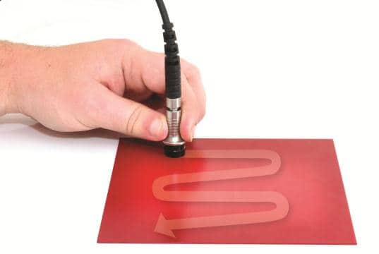
Using Scanning Technology to Acquire Higher Volumes of Data
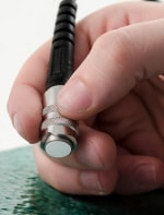
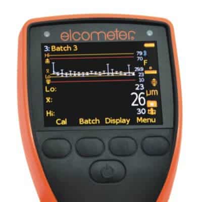
Several manufacturers of electronic coating thickness gages have incorporated “scanning probe” technology and the associated support software into the data acquisition process. This newer technology enables the gage operator to obtain large sets of coating thickness data in a relatively short time frame. For example, coating thickness data was obtained by a certified coatings inspector on an actual bridge recoating project that included 12 batches of readings (nearly 600 readings) in just under 8 minutes (measurement time only) on bridge girders across four panel points. So it may be possible to obtain a more representative sampling of the coated area without impeding production. However, there are concerns with acquiring such large data sets, such as management of the data, handling outliers, determining the statistical significance of the data (i.e., what is an acceptable standard deviation or coefficient of variation), applicability of the Coating Thickness Restriction Levels 1-5 in SSPC-PA 2), etc. The scanning probe set-up on the gage itself is relatively easy to perform, and the software is capable of handling the large volume of data coming into the gages.
The SSPC Committee on Dry Film Thickness Measurement may consider adding a 10th non-mandatory appendix to SSPC-PA 2 to give the specifier the option of acquiring a much larger data set of coating thickness measurements without impeding production. In this manner, an owner may gain greater confidence regarding the uniformity and consistency of the applied coating film.