
Unlike many industrial structures, ships often contain a variety of multi-layer coating systems on a single vessel, and even on the exterior hull itself, often including a complex sequence of anticorrosive layers followed by antifouling layers. This article focuses on the recoating of a ship’s exterior hull that resulted in catastrophic failure before the ship was ever returned to service.
THE BACKGROUND
The exterior hull coating on a large ship was installed about 25 years after its initial launch. Specifications required blast cleaning to SSPC-SP 10/NACE No. 2, “Near-White Blast Cleaning.” The hull was divided into three segments with each coating layer applied in a different color (Figure 1).
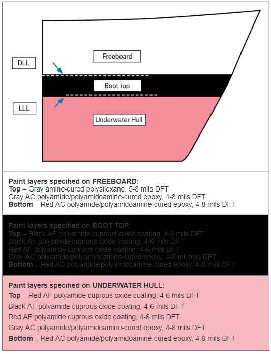
The underwater hull was to be coated with two layers (red, then gray) of an anticorrosive (AC) polyamide/polyamidoamine-cured epoxy at 4-to-8 mils DFT followed by three layers (red, black, then red) of an antifouling (AF) polyamide cuprous oxide coating at 4-to-6 mils DFT.
The boot top was to be coated with two layers (red, then gray) of the AC coating at 4-to-8 mils DFT followed by three layers of the AF coating (red, then two coats of black) at 4-to-6 mils DFT. This layer of the hull is sometimes above the waterline and sometimes under water, depending on weight. The light-load line (LLL) is considered to be 6 inches above the underwater hull and the deep-load line (DLL) 6 inches below the freeboard.
The freeboard (above the waterline) was to be coated with two layers (red, then gray) of the AC coating at 4-to-8 mils DFT, followed by a topcoat of amine-cured polysiloxane (gray) at 5-to-8 mils DFT to provide UV resistance.
After the coating work was completed, the ship was removed from the dry-dock and secured to a pier in the shipyard. Shortly afterwards, spontaneous peeling of the AF coating system from the AC coating was observed at various locations of the boot top around the perimeter of the ship. The peeling was most prevalent in an area from the DLL down approximately 3-to-4 feet around the perimeter of the ship. The AC coating beneath was intact and no rusting or deterioration of the AC was evident at any location.
Additionally, delamination of the coating was observed on the freeboard in an area from the top of the boot top up approximately 1-to-2 feet. This area was to have been coated with only the AC epoxy system and polysiloxane; however, there appeared to be an extraneous coat of the AF coating applied between the epoxy and polysiloxane. Two feet above the DLL, this same coating system showed no delamination, peeling or other notable defects.
FIELD INVESTIGATION
Samples were obtained from three locations within each area: a “lower” sample of the AF coating at or below the DLL and the intact AC coating beneath where the AF coating had been removed; a “middle” sample of any disbonded coating immediately above the DLL and the AC coating beneath the disbonded coating; and an “upper” sample of the freeboard polysiloxane. Figure 2 depicts the lower, middle and upper sampling locations.

Fig. 2: Lower, middle and upper sampling sites. The black area is the boot top.
In every case, upper samples of the freeboard polysiloxane coating were tightly adherent with no loss of adhesion between coats or to the underlying substrate. The AC coating beneath any disbonded AF or polysiloxane coating was also tightly adhered with no loss of adhesion between AC coats or to the underlying substrate
The adhesion of the AF coating to the underlying AC coating was somewhat variable, ranging from tightly adherent to relatively poor. There were large areas where the AF coating could be easily and cleanly separated from the underlying AC coating by cutting or scraping.
LABORATORY INVESTIGATION
The laboratory investigation focused on obtaining answers to two questions: 1) why did the red AF coating disbond from the gray AC coating over a large portion of the ship, and 2) why did the gray polysiloxane coating disbond in the middle area extending from the top of the boot top to approximately 1-to-1-½ feet above the DLL? The investigation consisted of microscopic examination, mix-ratio analysis by nitrogen content and infrared spectroscopy (IR), a recoat interval study, comparative batch composition testing, an analysis for the presence of an amine exudate (blush) and a solvent rub test.
Microscopic Examination
Cross-sectional microscopy of the samples collected during the field investigation revealed that the thickness of the gray AC coating ranged from 5.4-to-8.9 mils; the thickness of the red AF coating ranged from 3.2-to-7.7 mils.
The examination of coating chips from the middle area extending from the top of the boot top to approximately 1-to-1-½ feet above the DLL revealed an additional red coating layer between the gray intermediate coat and gray topcoat. A photomicrograph of one such coating chip is shown in Figure 3.

Fig. 3: Cross section of a paint chip obtained from within 1 1/2 feet above the DLL showing the extra red layer sandwiched between the gray layers at 200-times magnification.
Solvent Rub Test
A methyl ethyl ketone (MEK) rub test was used as a qualitative method to determine what coating was present on the backsides of the chips. Because it was known that the AF coating readily dissolved in MEK but the red AC epoxy primer did not, it was concluded that disbonding occurred within the AF layer.
Nitrogen Analysis: Mix Ratio
Nitrogen content analysis of the gray AC coating was performed to assess the mix ratio of the epoxy components. According to the product data sheet, Part A of the gray AC coating contained polyamide and polyamidoamine, both of which contain nitrogen. The Part B component consisted of an epoxy resin. The analysis revealed that two of the seven gray AC paint chip samples had a proper 1:1 mix ratio, and that the other five samples tested had excess nitrogen, with mix ratios ranging from 1.05:1 to as high as 2:1. The infrared spectroscopic analysis was also performed but did not provide any further information.
Recoat Interval Study
A study of the relationship between the application recoat interval and the adhesion of the red AF coating applied over the gray AC coating revealed that a two-hour recoat interval produced markedly better adhesion than did longer recoat intervals. The adhesion test involved making “X” cross-cut incisions through the coating layers of prepared and coated test panels, applying tape over the incisions and then removing the tape. The degree of adhesion was evaluated based on how much coating was removed by the tape. Figure 4 shows the coated panels after the testing was complete.

Fig. 4: Variations of adhesion with length of time between application of red AF and gray AC coating.
Tackiness / Tack-Free Test
The time of tackiness was defined as the interval between when the coating was no longer wet (when paint ceased to transfer to a fingertip that lightly touched the surface) and when the coating was no longer tacky. The coating was considered no longer tacky when a light touch to the surface ceased to leave an impression on the surface.
The results of the tackiness/tack-free study established that at 80 F air temperature and 65-percent relative humidity (RH), the proper 1:1 mixed gray AC coating had a tack window of 2.5 hours (Table 1). Mix ratios of 1.05:1 and 1.1:1 had a tack window of 2.25 hours; and a mix ratio of 1.4:1 had a tack window of 1-to-1.5 hours.
Table 1: Results of Tack-Free Study.

Batch Composition Testing
Paint retained from the original application was compared to control samples provided by the coating manufacturer, and compositional values were found to be reasonably consistent. Unfortunately, original samples of the red AF coating and the Part A component of the gray AC coating were not available for testing.
Amine Exudate Analysis
Infrared spectroscopic analysis was performed to determine if the gray epoxy AC coating had developed an amine exudate prior to application of the red AF coating that contributed to the poor adhesion characteristics. Because the surface of the gray epoxy was contaminated with trace residuals of the red AF containing a polyamide component, the presence or absence of amine blush could not be conclusively determined.
CONCLUSIONS
There were numerous areas around the perimeter of the ship, particularly on the port side but also on the starboard side and stern, where spontaneous disbonding and relatively poor adhesion of the black AF coating was occurring. This disbonding affected the greatest surface area and was the coating problem/failure of greatest concern.
During sampling, it was ascertained that adhesion of the AF coating system to the underlying AC coating system was variable, ranging from spontaneous disbonding in large areas to relatively tight adhesion in other areas.
It was concluded that the poor adhesion and disbonding occurred as a result of application of the red AF first coat over the gray epoxy AC topcoat, after the gray epoxy was no longer tacky.
The adhesion variability of the AF coating observed during the course of sampling, and at least visually on portions of the ship’s hull, almost certainly was a result of the variable tackiness of the underlying gray AC topcoat. Where there was a long tack time, suitable adhesion occurred. Where the AF coating was applied after the tack time had been exceeded, there was moderate to lower adhesion.
Testing also established that when there was an excess amount of Part A in the mix, the tackiness time of the gray epoxy AC coating was reduced, effectively reducing the tack window and further aggravating the adhesion problem.
SUMMARY
The spontaneous disbonding that impacted the largest area occurred where the red AF coating was applied over the gray AC coating, in the area between the deep-load line (DLL) and the water. The cause of this problem was attributed to the application of the red AF coating after the tackiness window of the gray epoxy AC coating had expired. The recoat interval study of the red AF coating applied over the gray AC coating revealed that the red AF coating had markedly better adhesion when applied two hours after application of the gray AC coating than when applied four hours and 40 minutes, six hours or eight hours after application of the gray AC coating. The tackiness/tack-free test revealed that the tackiness window of the gray AC coating was 2.5 hours. A review of the painting records revealed that the red AF coating was often applied more than 2.5 hours after the gray AC coating. Adequate adhesion would not have been achieved in these areas.
Nitrogen and infrared spectroscopic analyses of samples of the gray AC coating and controls prepared at various mix ratios indicated that much of the gray AC coating applied to the hull had an excess amount of Part A, the pigment component that contained the polyamide and polyamidoamine resins and associated solvents. The tackiness/tack-free test established that when there was an excess amount of Part A, the tackiness time of the gray epoxy AC coating was reduced, further aggravating the adhesion problem.
A secondary coating problem was the spontaneous disbonding of the gray polysiloxane topcoat from the AC coating system in the area immediately above the DLL to approximately 1-to-1-½ feet above the DLL. The adhesion of the gray polysiloxane topcoat to the gray AC coating was excellent in the areas above this region. Cross-sectional microscopic examination of coating chip samples revealed that one or more layers of the AF coating had been inadvertently applied to numerous areas above the DLL. When the polysiloxane was applied down to the DLL, the AF was not removed, but covered over. Disbonding occurred between the red AF layer and the gray epoxy topcoat of the underlying AC coating for the same reasons as described earlier for the spontaneous disbonding and poor adhesion of the AF coating to the underlying AC coating below the DLL.
 ABOUT THE AUTHOR

Robert Leggat is the KTA Laboratory Services Manager and has over 15 years of experience in the protective coatings industry. He holds a PhD in Materials Science and Engineering from the University of Virginia and successfully completed the KTA Level I Basic Coatings Inspection training course. Mr. Leggat joined KTA in August 2016 as the Laboratory Services Manager overseeing the operations of the Analytical and Physical Testing Laboratories. In this position, he oversees all laboratory services which include paint, corrosion and material testing services, coating failure investigations, coatings research, and compositional analysis. Under his oversight, senior chemists, chemists, and research and development specialists provide clients with independent, accurate analyses of coating problems and advance the industry’s understanding of the performance characteristics of protective coatings and abrasive media. Prior to joining KTA, Mr. Leggat held various senior research and technical management positions with the United States Steel Corporation in Pittsburgh, PA.
Very detailed and well documented case study and totally makes sense if you are familiar with the marine DD industry.
Seems like all the epoxies would still in the curing-phase and the recoat window would still be open especially for a polyamide resin within these short timeframes. I do not see how a legitimate conclusion can be drawn on adhesion. Pull-off tests are to be performed on cured coatings. It might be a different case if it was a fast cure product like a sprayed polyurea.
Mr. Moran – the following comes from the author, Rob Leggat:
Thank you for your comments on the article. The tack time study showed that the recoat window was sensitive to the resin to hardener ratio which reduced it from 3 ½ hours to 1 ½ hours for the mix ratios we observed. The adhesion test were conducted on full cured coatings. The variable in that study was the recoat window between application of the epoxy coating and the antifouling coating. This study showed the impact on adhesion of exceeding the recoat window.
Best regards,
Rob