
Section loss of pipe wall is of great concern in the pipeline industry. Reduced wall thickness due to pitting corrosion can adversely impact pipeline integrity; the results of which can be catastrophic depending on the product that the pipeline is transporting. In order to reduce the opportunity for corrosion, the use of protective coatings is often supplemented with impressed current cathodic protection (CP) systems to protect the pipe from corrosion, pitting and eventual perforation in the event of a breach in the protective coating system. In the instance discussed in this article, a pipe section that was excavated displayed severe pitting despite the application of a proven powder coating system and the installation of an impressed current CP system.
A section of pipeline needed to be excavated in a relatively small area to accommodate new construction in the surrounding area. The pipeline was buried and put into service only about six months earlier, so corrosion and coating failure were not expected. However, failure of the powder coating system and severe pitting was evident on the excavated pipe section. The pipeline owner was notified to witness the excavation and to examine the condition of the pipe.
After the initial section of pipe was excavated, additional lengths of pipe were exposed to determine the extent of the corrosion which was occurring in relatively deep pits that appeared randomly on the pipe sections in two areas. The other sections of excavated pipe revealed no visible corrosion. A section of the 24-inch pipe was removed and replaced (cover image). From this section a smaller 15-by-48-inch section was delivered to the laboratory along with a copy of the specification governing the application of the powder coating.
EXAMINATION
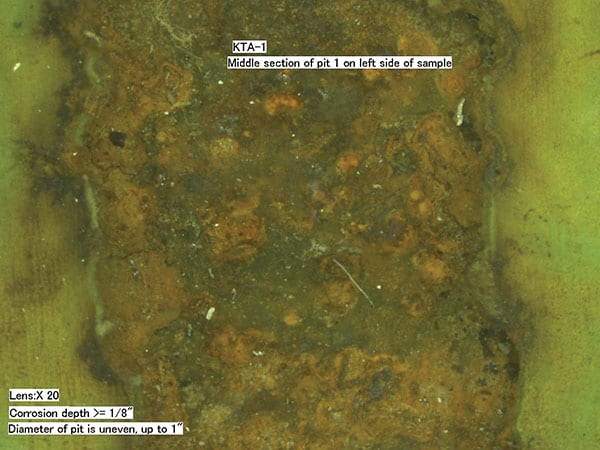
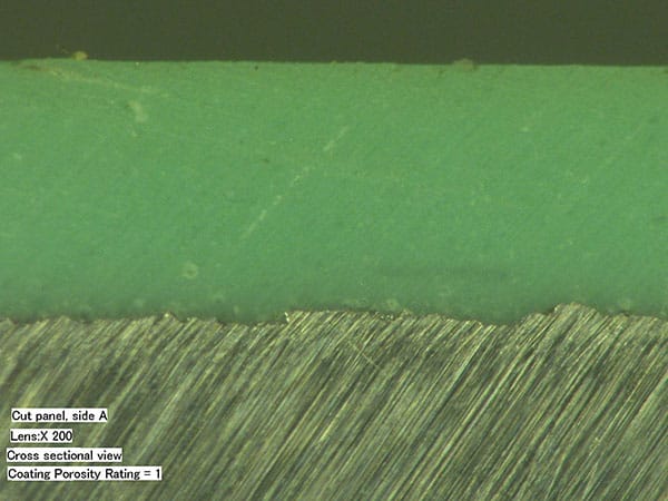
Upon receipt at the laboratory the pipe section was cut into four small pieces that contained the corrosion pitting. The sections were examined using a digital microscope (Figure 1). Although there was some porosity within the thickness of the coating layer, it appeared near the metal interface, which is common. The application of the powder coating met the requirements of the specification with a porosity level of 1, as rated in the Canadian specification Z245.20-06, “Plant-applied external coatings for steel pipe” (Figure 2).
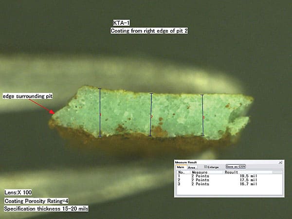
The coating thickness was measured using the same digital microscope. The thickness of the powder coating ranged from 15.2-to-20.2 mils in the seven areas measured. An example of the thickness is shown in Figure 3.
These initial findings were in contrast to the condition of the pipe in the pitted areas, especially considering the degree of corrosion and the depth of the pits noted on the pipe. The depth of the pits varied measuring up to 1/8-inch into the thickness of the ¼-inch-thick pipe, even though it had only been in service approximately six months.The thicknesses measured were within the specified range. The coating material was tightly adhered to the metal substrate, even adjacent to the areas displaying corrosion. A combination of scraping and chemicals had to be used to remove the powder coating and expose the underlying substrate. The roughness of the steel (created by the abrasive blast cleaning process prior to application of the powder coating) was measured using replica tape and was approximately 3 mils, which was also within specification. The newly exposed metal surface was clean and shiny (Figure 4).

WAS THE CORRECT COATING APPLIED?
Infrared (IR) spectroscopy is frequently used to determine the cure of liquid-applied coating materials; however this analytical technique can tell little about the cure of standard powder coating materials. As a result IR spectroscopy was used to confirm that the specified generic type of powder coating material had been applied.
For this analysis, a small amount of the raw powder supplied by the manufacturer was analyzed and the resulting spectrum was compared to a spectrum of the material from the pipe section. This analysis was critical since powder materials frequently require different bake temperatures and dwell times to achieve the final film properties. If an alternate material was supplied and applied to the pipe, the bake time and temperature recommended for the specified material may have been different and new parameters and material would be needed to perform further laboratory analysis. Confirmation of the coating type meant that the specified bake time and temperature were known.
WAS THE POWDER COATING CURED?
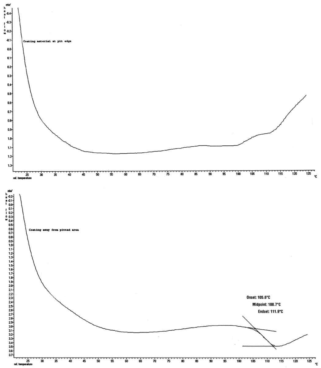
While the application information supplied by the owner indicated that the proper bake time and temperature were followed. Differential scanning calorimetry (DSC) was performed to confirm the cure state of the powder coating. For this technique, small amounts of the material are heated and the reaction of the product to the heat is used to create heating curves and the glass transition temperature (Tg) can be determined from the heating curves. The glass transition temperature changes with the degree of cross-linking of the material. Most powder coatings have an optimum glass transition temperature to achieve optimum properties of the coating material. If the glass transition temperature of the applied material varies from the stated glass transition temperature, it is an indication of improper cure during the post-application baking process.
Table 1 – Glass Transition (Tg) Results
| SAMPLE | LOCATION | GLASS TRANSITION (TG) |
| Pipe | Away from pit, top | 105.6 |
| Pipe | Away from pit, bottom | 105.3 |
| Pipe | Pit 1, edge | 98.5 |
| Pipe | Pit 2, edge | None visible |
| Control Powder | After bake | 106.3 |
Glass transition temperature results indicated that the coating material on the majority of the pipe section displayed a Tg that was within the temperature range expected for the properly cured material (Table 1). However, there was some difference noted when the material was sampled at the spots where corrosion was occurring. The proper glass transition event is noted on the lower of the two heating curves, while an area that displayed no glass transition is portrayed in the top heating curve (Figure 6).
This was considered peculiar, since it would be essentially impossible to have small spots on the pipe where the bake conditions (i.e., temperature and dwell time) were different enough to lead to variations in cure. Rather, this seemed to indicate that the powder coating material was somehow being affected in these isolated areas, resulting in a change in the cross-link density after the pipe was put into service.
WHAT ABOUT SURFACE CONTAMINATION?
Elemental examination of the surface for contamination was the next step in the investigative process. However, in order to examine the surface, the coating (that was very well adhered to the steel) had to be removed. Smaller sections (strips) cut from the pipe were placed in a freezer to cool the metal to -40 C. The individual sections were removed and a press was used to quickly bend the strips over a narrow mandrel. The rapid, forced bending at a cold temperature caused the material to release cleanly from the surface.
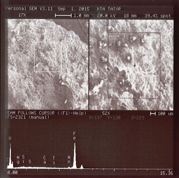
The newly exposed metal was then analyzed for elemental variations using a scanning electron microscope (SEM) outfitted with energy dispersive X-ray spectroscopy (EDS) (Figure 5). This technique is not as sensitive as some other techniques for examination of surface contamination, but since the coating was so tightly adhered it was difficult to expose the larger surface areas that are required when employing other surface analysis techniques.
The elemental scans did not reveal the presence of high levels of chloride or sulfur that may be associated with salt contamination. These scans confirmed that the surface was clean prior to application of the powder coating.
WHAT DOES HIGH PH INDICATE?
The pH of water placed inside one of the pits revealed an alkaline condition. Since the pipe section had been handled and the pH condition was not reproduced by other pitted areas, this was hardly compelling evidence but was considered a clue nonetheless. In hindsight, measuring the pH in the pitted areas in the field, before the pipe was handled, would have proven valuable. Interestingly, areas subject to cathodic disbondment typically produce an alkaline condition.
DO WE HAVE PROBABLE CAUSE?
The results of the laboratory analysis in conjunction with admittedly circumstantial evidence led to the opinion that the cause of the aggressive pitting was most likely stray current corrosion.
The corrosion was considered severe, due to the short time of service. This was of great concern to the owner, so a site visit was performed by an investigator to determine if any more information about the service environment could be uncovered. The investigator was able to discover several interesting pieces of information.
First, while an impressed-current CP system was in place, it was not being monitored. The initial setting was “standard” and may not have been appropriate for the conditions at that site. Second, there were tanks with impressed-current CP systems nearby and power lines were present in the area where most of the severe pitting was occurring. All of these external influences can adversely impact the effectiveness of the cathodic protection intended for the pipe. Monitoring the CP system and noting the areas of higher or lower resistance can help to prevent stray current corrosion. The installation of a monitoring system for the impressed-current CP system was discussed with the owner to determine the changes in the current density and attempt to offset the effect of the stray currents. Additionally, some degree of isolation from the other sources was deemed necessary for the temporary protection of the pipeline.
Finally, the quality and consistency of the backfill was discussed. Changes in the backfill material can alter the resistance of the soil surrounding the pipe, and changes in temperature of the material within the pipe can change the requirements of the cathodic protection along the pipeline. These variations can initiate corrosion in small defects that would typically be protected by the CP system. The resulting small areas of intense corrosion due to variations in current density would appear similar to pitting caused by stray currents.
As seen in JPCL February 2016 (slightly modified)
ABOUT THE AUTHOR

Valerie Sherbondy is the technical manager for the analytical laboratory for KTA-Tator, Inc., a consulting and engineering firm specializing in industrial protective coatings. Sherbondy has been employed at KTA since 1990 and has provided laboratory support for the investigation of hundreds of coating failures and coating testing programs. She holds a B.S. in chemistry from the University of Pittsburgh and is an SSPC-certified Protective Coatings Specialist, a member of the American Chemical Society (ACS) and a committee chair for NACE International.
NICE ARTICLE
Your articles are great I read then all. I am looking for a meter to check stray currents on tugs and work barges, I am told a fluke meter, I would need leads of about 50 to 75′ each. Can someone direct me please.
Tommy, thanks for the kind words about our site & articles! I’ll have someone from our KTA Gage Instrument Sales Department reach out to you in regards to your inquiry.
Thanks,
Jason
KTA Marketing Department