ANSI/ASHRAE/IES Energy Standard 90.1-2010 and the 2012 International Energy Conservation Code require that building envelopes be designed to limit uncontrolled air leakage into and out of buildings. Air leakage in buildings is controlled at the time of construction by installing air barrier systems. ASTM E1186-17, “Standard Practices for Air Leakage Site Detection in Building Envelopes and Air Barrier Systems” defines an air barrier system as “a system in building construction that is designed and installed to reduce air leakage either into or through a building envelope.”
ASTM E1186
ASTM E1186 describes seven practices for detecting air leakage sites in building envelopes to determine if a functional air barrier system has been installed. Five of the methods test the entire building and are performed at the completion of construction. The remaining two methods are designed for localized testing, and are used when depressurizing or pressurizing the entire building is impractical.
One of the two ASTM E1186 methods of localized testing, Chamber Depressurization in Conjunction with Leak Detection Liquid, is particularly useful during construction to examine the effectiveness of the installation in configurations that typically create the greatest challenges for air tightness, such as joints between materials, penetrations through membranes (e.g., brick ties), and the seams of roof membranes. Also, since the IECC recognizes paint as an air barrier when applied to concrete masonry units (CMU), this method can be used to assess the continuity of the coating to make certain the porous masonry surface is completely sealed. Although not addressed in ASTM E1186, the instrument can also be used to detect locations of water leaks.
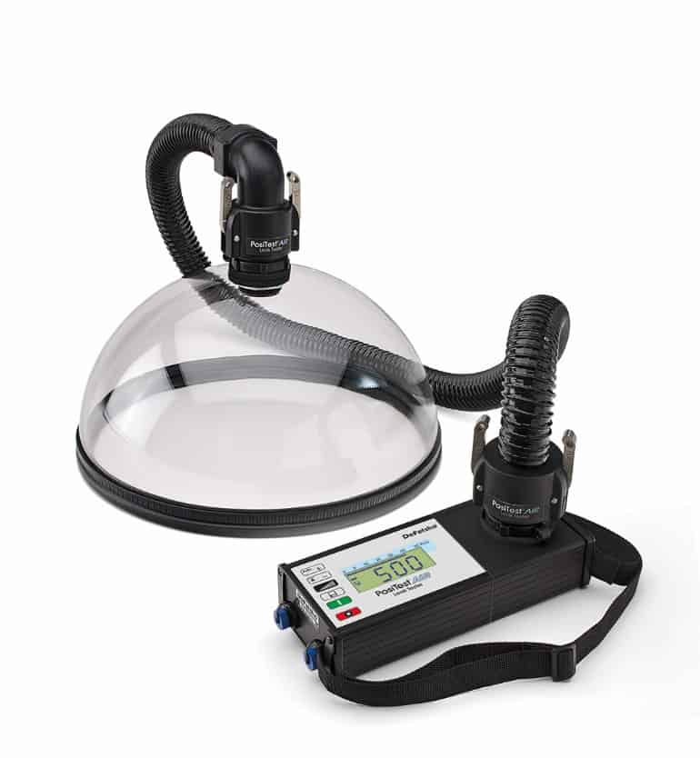
The PosiTest® AIR Leak Tester meets the requirements of ASTM E1186, Chamber Depressurization in Conjunction with Leak Detection Liquid. The requirements of this method, as stated in ASTM E1186, are as follows (the text in the brackets and photos have been added by KTA – they are not part of the standard):
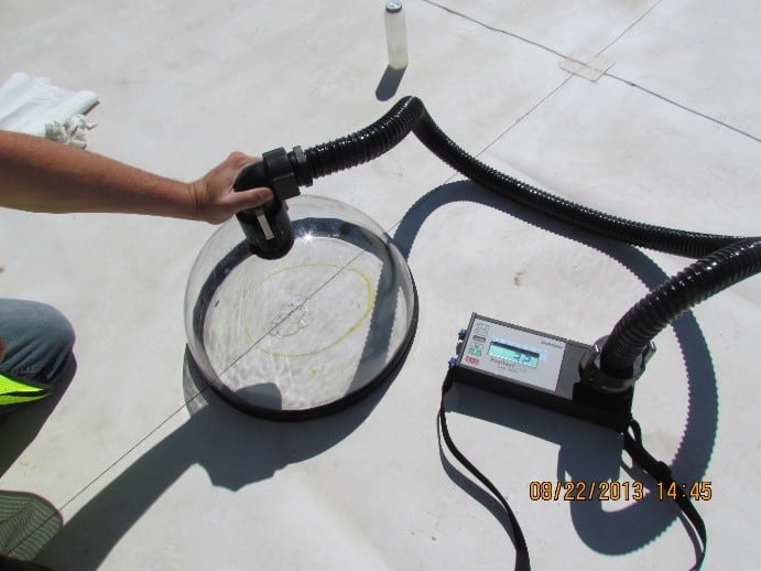
Leak Detector Liquid in Conjunction with Depressurized Chambers Practice—This practice relies on the principle that a pressure differential across a liquid film at an air leakage site will form bubbles in the film. The film is located on the low pressure side of the specimen within a transparent test chamber to allow visual observation of the test specimen during the test.
7.8.1 Background—This practice is suitable for locating air leakage sites at specific details when depressurizing or pressurizing the entire building envelope is impractical, and enables the testing of penetrations and joints in rigid air barrier materials such as metal liners or membranes supported by rigid substrates. The practice subjects a test specimen and the surrounding area to a desired pressure differential which is limited by the structural capacity of the specimen.
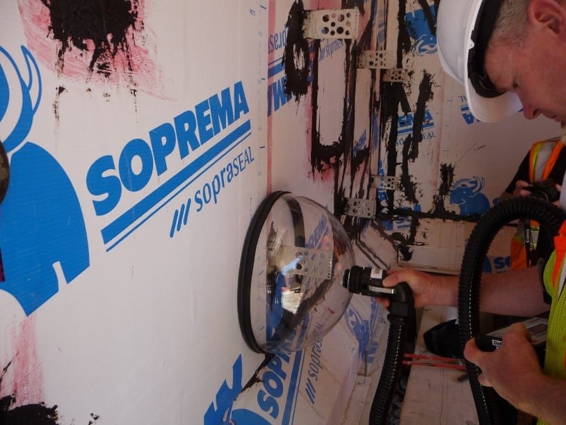
[Photo 2 shows testing of penetrations during construction.]
7.8.2 Test Chamber—The test chamber consists of a well-sealed, transparent chamber which is capable of resisting the pressure differentials of the test. The chamber must be sufficient in size to enclose the test specimen. .A pressure tap may be installed to allow the measurement of the pressure differential across the specimen during the test with a manometer.
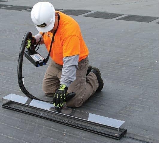
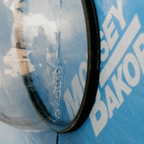
[Photo 3 shows a test chamber designed for examining seams in roofing. The pressure differential is programmed directly into the instrument. It does not require the use of an external manometer.]
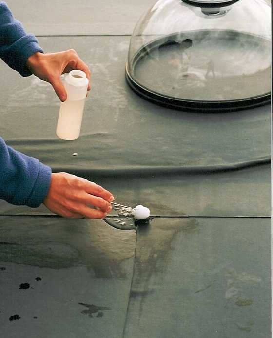
7.8.3 Leak Detector Solution—A leak detector liquid which can be easily applied over the test specimen surface may be used. The viscosity should be sufficient so that the liquid remains in an even coat on the test specimen during the test. Bubbles should not form in the liquid during application.
[Photo 4 shows the application of a leak detector liquid to the test area.]
7.8.4 Air Exhaust System—The air exhaust system consists of a fan which is able to provide sufficient airflow to achieve the desired pressure differential across the test specimen. A means of increasing the airflow at a rate of approximately 25 Pa/s or less enables the bubbles to form gradually without breaking at large air leakage sites.
7.8.5 Details—The leak detector liquid is applied evenly over the surface of the test specimen and the test chamber is fitted over the specimen and sealed to the surrounding air barrier system. Care must be taken so that bubbles are not formed in the liquid by the application technique. The fan is used to extract air from the test chamber until the desired pressure differential across the specimen is reached. Bubbles or visible distention of the leak detector liquid indicates the existence of air leakage sites through the air barrier system. An estimate of the relative size of the leak can be made based on the size and speed with which the bubbles form.
[Photo 5 shows the instrument display and the formation of bubbles at a leakage site. Pressure differential can be set up to 900 Pascals (Pa) in 100 Pa increments, with the rate of depressurization set from 5 Pa/sec to 30 Pa/sec in 5Pa/sec increments. The instrument will run until the preset pressure differential is reached. Common values are a pressure differential of 500 Pa and a rate of depressurization of 25 Pa/sec, which translates to a test time of 20 seconds. Note that 500 Pa is not a great pressure differential. It is approximately 10 pounds/square foot. The report section of the standard makes documentation of the pressure differential mandatory, which is recorded directly from the display on the instrument.]
7.8.6 Limitations—A knowledge of potential air leakage sites is necessary to limit the search
area using this practice. This practice is only suitable when the air barrier system is accessible and has sufficient rigidity that it is not pulled into the test chamber during the test. Care must be taken during the test that air leaks at the seal between the test chamber and the air barrier system are not confused with air leakage sites through the test specimen.
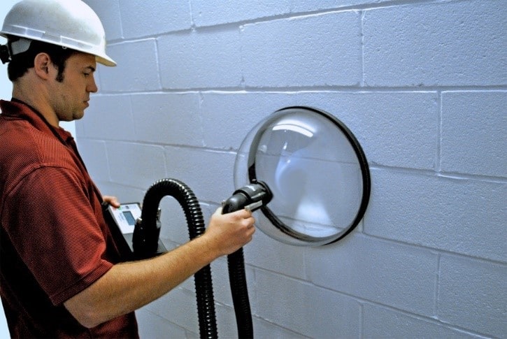
Even if one of the “whole building” tests will be used upon completion of the structure, localized testing during construction will help to identify processes that need to be improved while the work is in progress to avoid having to repair joints or seams, or repaint a CMU wall after-the-fact. It is also a valuable tool for use during periodic audits to complement visual inspections and adhesion testing. Photo 6 shows the identification of an incomplete joint between materials. By identifying it during construction, changes can be made. Photo 6 shows the instrument being use on a CMU wall to determine if the application process is sound.
Summary
ANSI/ASHRAE/IES Energy Standard 90.1-2010 and the 2012 International Energy Conservation Code require that building envelopes be designed to limit uncontrolled air leakage into and out of buildings ASTM E1186 provides seven methods for verifying that these mandates have been achieved. One of the methods, Leak Detector Liquid in Conjunction with Depressurized Chambers, is an excellent means for verifying the quality of installation while the work is being performed, so that changes to the installation process can be made to achieve compliance. The PosiTest® AIR Leak Tester complies with this method. The following link contains a video that describes the instrument and demonstrates its use: https://www.youtube.com/watch?v=zQnDhwgpM7M