According to SSPC: The Society for Protective Coatings, Paint Application Standard No. 2 (SSPC-PA 2), Procedure for Determining Conformance to Dry Coating Thickness Requirements, is one of the most frequently downloaded standards from the SSPC Marketplace. Measuring coating thickness is one of the most commonly specified quality control processes, and SSPC-PA 2 is recognized across the globe as the standard for frequency and acceptability of coating thickness measurements. SSPC-PA 2 was first published as a temporary standard in 1973 and has undergone many revisions over the years.
While the body of the standard is reasonably well recognized, there are several nonmandatory appendices that provide guidance on several unique measurement issues that may be a little less known. Although they are not mandatory as part of the standard, they can be made mandatory by invoking them in the contract documents (specification). The appendices include:
- Appendix 2 – Methods for Measuring Dry Film Thickness on Steel Beams (Girders)
- Appendix 3 – Methods for Measuring Dry Film Thickness for a Laydown of Beams, Structural Steel, and Miscellaneous Parts after Shop Coating
- Appendix 4 – Method for Measuring Dry Film Thickness on Coated Steel Test Panels
- Appendix 5 – Method for Measuring Dry Film Thickness of Thin Coatings on Coated Steel Test Panels that Have Been Abrasive Blast Cleaned
- Appendix 6 – Method for Measuring the Dry Film Thickness of Coatings on Edges
- Appendix 7 – Method for Measuring Dry Film Thickness on Coated Steel Pipe Exterior
- Appendix 10 — Procedure for Obtaining a Greater Population of Thickness Measurements Using Type 2 Gage Continuous Read/Scanning Probe Technology
Other appendices that are more informational include:
- Appendix 1 – Numerical Example of Average Thickness Measurement and Illustration of the Procedure for Determining the Magnitude of a Nonconforming Area
- Appendix 8 – Examples of the Adjustment of Type 2 Gages Using Shims
- Appendix 9 – Precaution Regarding Use of the Standard for Coating Failure Investigations
This article focuses on Appendix 10, Procedure for Obtaining a Greater Population of Thickness Measurements Using Type 2 Gage Continuous Read/ Scanning Probe Technology that was added to SSPC-PA 2 in November 2018.
Research conducted in 2016 by Vision Point Systems, Inc. in conjunction with the US Naval Research Laboratory[1] demonstrated that greater precision of DFT measurements can be obtained using a scanning probe method over the traditional “place and remove” probe method. The research also indicated that the increase in precision of rapid scanning DFT measurements over the traditional measurement frequencies described in PA 2 can be substantial. Rapid DFT scanning technology enables an operator to collect a larger number of measurements in a shorter time frame than the traditional method. As a result of the increased number of measurements collected, better estimates of the sample mean can be obtained through increased precision. The research lead to three recommendations to the SSPC Dry Film Thickness Committee in 2017:
- Incorporate scanning DFT measurements into SSPC-PA 2;
- Develop and implement scanning DFT gage/probe accuracy verification schedules for greater DFT data precision, since probe wear can adversely affect the reliability of the coating thickness data; and
- Establish a minimum batch size that is dependent on the level of precision desired, time constraints, and the risk of coating failure.
Rather than invoke such a drastic change to a 45-year old standard, the committee elected to describe the new procedure in a non-mandatory Appendix. This allows the historic measurement techniques of SSPC-PA2 to remain unchanged, while providing the option for users to mandate the scanning probe/continuous read technique on a project-specific basis by invoking Appendix 10 in the contract – e.g., “Coating thickness shall be measured and documented in accordance with SSPC-PA 2, Appendix 10.” Appendix 10 provides a protocol for measuring the DFT of coatings with Type 2 (electronic) gages using scanning technology. Several gage manufacturers offer scanning probe and continuous read devices.
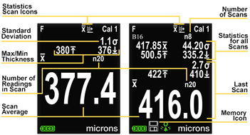
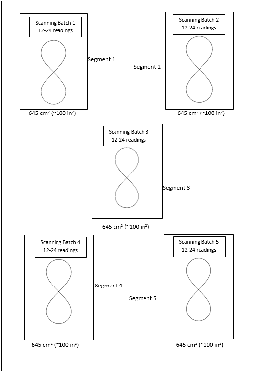
Two definitions applicable to Appendix 10 include: Scanning Batch Measurement, which is defined as the mean of no less than 12 DFT readings and up to 24 readings without lifting the probe from the coated surface, using an “infinity symbol motion” ∞ [vertical or horizontal orientation] obtained within a 645 cm2 (~100 in2) segment of the coated area; and Scanning Area Measurement, which is the sample mean of five scanning batch measurements obtained over each 10 m2 (~100 ft2) area of coated surface, or portion thereof.
The procedures for gage calibration, verification of accuracy, and adjustment described in Section 5 of the SSPC-PA 2 standard do not differ when using scanning probes and continuous read-out gages and need to be completed prior to acquisition of coating thickness readings described in Appendix 10. One could argue that verification of accuracy is even more critical due to a greater potential for probe wear since it is moved across the surface rather than being lifted after each reading. It is important to follow the gage manufacturer’s instructions when verifying gage accuracy and adjusting the gage, particularly when instruments equipped with a probe wear cap are used.

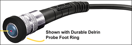
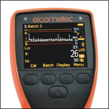
Elcometer Ultra-Scan Probe with Wear Cap
After the coating has sufficiently dried, the special wear-resistant probe (or probe equipped with a wear cap) of a Type 2 gage (preset to the continuous read mode) is traversed across the surface using an “infinity symbol motion” [∞], within a 645 cm2 (~100 in2) segment at a rate necessary to obtain a minimum of 12 readings and a maximum of 24 readings before lifting the probe. While more than 24 readings may be acquired during the scan, the research described
earlier in this article indicated that there is little improvement to the statistical validity of the data set with additional readings beyond 24. Any unusually high or low gage readings in a scan batch that are not repeated consistently can be discarded. The mean of the acceptable readings (Scanning Batch Measurement), as well as highest and lowest readings (after discarding outliers, if applicable) are reported. The standard deviation may also be reported if required.
This procedure is repeated in four additional 645 cm2 (~100 in2) segments (total of five segments) over each 10 m2 (~100 ft2) area of coated surface, or portion thereof. The same Coating Thickness Restriction Table (Table 1) provided in Section 9 of the SSPC-PA 2 Standard (shown below) is used to verify conformance to the coating thickness specified in the contract documents. The “Spot Measurement” column that is used with the traditional SSPC-PA2 three-gage readings is also used to determine the acceptability of the Scanned Batch Measurements.
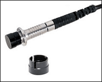
Defelsko Scanning Probe with Foot Ring

The total mean of the five scanning batch measurements obtained over each 10 m2 (~100 ft2) area of coated surface, or portion thereof is recorded as the “Scanning Area Measurement.” In this case, the “Area Measurement” column in the Coating Thickness Restriction Level Table is used to determine the acceptability. A diagram (excerpted from SSPC-PA 2 [November 1, 2018]) illustrating scanning batch measurements and scanning area measurements is shown below.
The only significant difference between the scanning
probe techniques and the traditional method of measurement per SSPC-PA 2 is the
number of readings composing the spot (3 gage readings in the case of
traditional SSPC-PA2 versus 12 to 24 for the scanning probe), and the size of
that spot (1.5-inch diameter for traditional SSPC-PA2 measurements and 645 cm2 (~100 in2) for the
scanning probe). Essentially everything
else is the same, including the number of scanning batch measurements per 10 m2 (~100
ft2) area (5) and the number of 10 m2 (~100
ft2) areas to be measured.
[1]Paper No. 334110 – 2017 Department of Defense – Allied Nations Technical Corrosion Conference – Statistical and Technical Evaluation of Rapid Dry Film Thickness (DFT) Measurement Technologies; Jeff O’Dell, Wayne McGaulley, and Evan Parson: Vision Point Systems, Inc.; John Wegand, Paul Slebodnick, and Jimmy Tagert: U.S. Naval Research Laboratory.