Surface preparation and painting the interior of tank structures is sometimes viewed as one of the more easily completed industrial painting endeavors. While it is true that for most tank interiors, the structure itself comprises the containment, there are no logistics involved with traffic restrictions or other trades working in the same areas, and the majority of surfaces to be prepared and painted are large and flat as opposed to intricate members with many edges, corners, and tight spaces. The fact is that interior tank painting work is often difficult due to confined space safety, worker access to all tank surfaces, short available timeframes to complete the work when the tank can be removed from service, and unforeseen delays after abrasive blast cleaning reveals excessive pitting or structural damage.
Even the best structure owners or industrial painting contractors cannot account for all unforeseen difficulties when planning a tank interior coating project. However, one thing that can be done to ease project execution is controlling the ambient conditions inside the tank.
The goal of a dehumidification system as part of an abrasive blasting and painting project is to limit surface contamination and to control the ambient conditions (i.e., temperatures and relative humidity) during surface preparation, coating application, and paint material curing in an effort to maximize the coating life of the tank lining. Controlling the ambient conditions within the tank will also enable crews to work in adverse weather conditions that would otherwise stop work, allowing crews to avoid delays and re-work (e.g., re-blasting areas of flash rust due to high humidity). Specifications and coating manufacturers’ product data sheets will specify an acceptable temperature range and relative humidity (RH%) for surface preparation and coating application. Dehumidifiers and heaters can be utilized to control environmental conditions inside tanks. Controlling ambient conditions can be beneficial to meet many objectives. These objectives include extending the painting season, reducing rust-back of prepared steel, cleaning and painting during adverse weather conditions especially when a project is time sensitive, and reducing rusting of steel abrasives (if used). In particular for tank interiors, the difficulty in daily abrasive and dust cleanup prior to prime coat application can be reduced or, depending on the tank, be eliminated. If the entire interior can be abrasive blast cleaned without rust-back before priming begins, significant time and therefore money can be saved.
Determining what dehumidification system equipment is needed (i.e., sizing) for tanks interiors or other structures can be very simple or quite involved based on what you wish to achieve. Often recommendations from equipment manufacturers or rental suppliers are sufficient. For larger or longer projects with a wide range of possible weather conditions, or with narrow specified application conditions, it is advisable to perform a more detailed analysis using thermodynamics and psychometrics.
The most simplified method for determining how much conditioned (e.g., dehumidified) airflow that is required is to assume that 3 to 4 air changes per hour will provide the desired conditions for surface preparation, painting, and curing. For tanks with few openings or potential outside air intrusions, 3 air changes with conditioned (dry) air will often suffice. To determine the airflow required from the dehumidifier (in cubic feet per minute or CFM), see the following example for a circular above ground storage tank with a diameter of 50-feet and a shell height of 48-feet (assume 3 air changes per hour).
Tank Volume x Air Changes per Hour / 60 minutes per hour = Conditioned Air Flow Rate
(pD2/4) H x 3 / 60 = Q
(p502/4) 48 x 3 / 60 = 18,850 CFM
Note that the tank volume can also be determined from the tank capacity in gallons divided by 7.48 gallons per cubic foot. Therefore, as a first approximation, for estimating, or for a small job, a dehumidification unit that can supply at least 18,850-CFM of dry air will provide conditions for painting. Equipment rental suppliers will inquire if the work is to be done in hot weather or cold weather to decide what type of dehumidification equipment is needed. If tank exhaust ventilation is also being used to provide dust collection or ventilation to limit explosive hazards, the same volume of exhaust ventilation airflow should be used (e.g., dry air into the tank should equal exhaust air out of the tank).
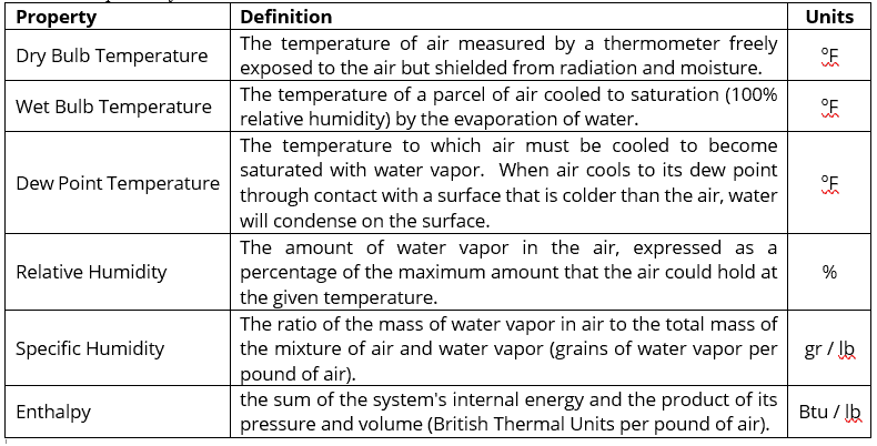
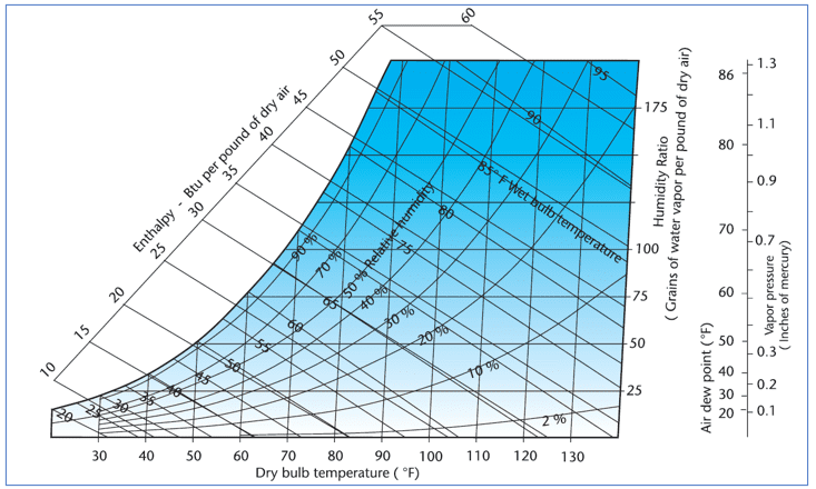
A detailed sizing will account for all the project specific conditions and requires more extensive calculations. In some cases, these calculations may require a qualified professional. For more refined dehumidification equipment sizing, the practice of humidity control requires a familiarity with properties and behavior of moist air. Refer to the following definitions in Table 1. These properties are used in conjunction with the psychrometric chart shown in Figure 1.
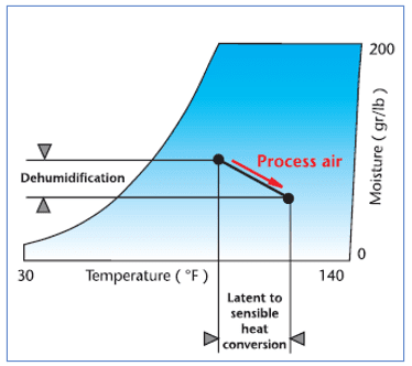
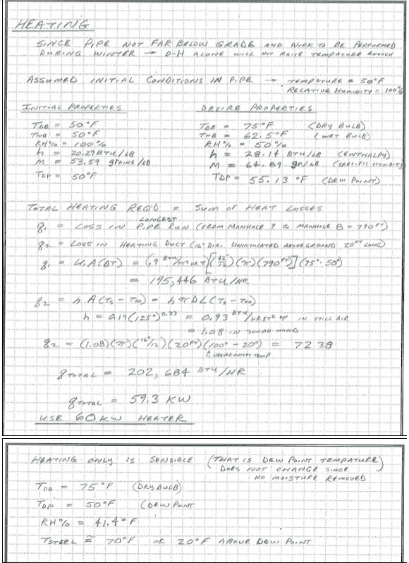
While technically not a dehumidification process (since moisture is not being removed), heating alone can reduce the relative humidity within an enclosed work area quite well when temperatures are cold (e.g., near or below freezing). This is because hotter air can hold more moisture and the ventilation system removes the moisture laden air. When ambient temperatures are higher however, the effectiveness of the heating alone to control ambient conditions diminishes since the increase in temperature needed becomes excessive. Additional heat in an enclosed work area when it is already hot and humid would not only be uncomfortable for the workers, the moisture load within the enclosure would also increase from increased worker perspiration and respiration.
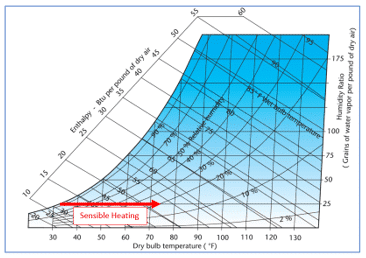
Figure 2 – Sensible Heating – Heating the Tank Interior
Reduces the Relative Humidity
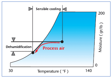
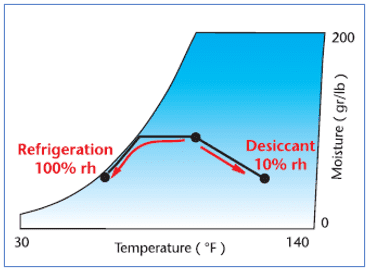
There are many types of dehumidification (DH) systems, including cooling-based dehumidifiers (e.g., direct expansion, chilled liquid systems, etc.) and desiccant type dehumidifiers (e.g., liquid spray tower, solid packed tower, rotating horizontal bed, rotating wheel). Chiller type dehumidification would be useful for the tank projects only when the relative humidity is high, and the temperature is also high. Alternatively, a desiccant wheel dehumidifier uses an electric or LP gas heater to reactivate the desiccant material within the rotating wheel and provides good performance in both cold and hotter temperatures. Desiccant wheel dehumidifiers are the most commonly used dehumidification type for industrial painting projects. This is because the moisture removal capacity is high, the design is energy efficient, and the equipment is simple, reliable, and easy to maintain. Disadvantages of the desiccant wheel dehumidifier is that in hot weather it is less efficient at reducing moisture and will increase the overall temperature inside the tank somewhat. Each process is shown on the psychrometric chart in the following figures along with a comparison of cooling-based dehumidification versus desiccant dehumidification.
Detailed calculations are needed to address the project specific conditions. Examples are included below for various weather conditions, and when more than one type of equipment is needed. The equipment selection (type of dehumidification system) should be based on the anticipated weather conditions; heating alone for cold weather (e.g., below 40oF), chiller or direct expansion dehumidification for hot weather (e.g., above 70oF), and a desiccant wheel dehumidification system for a wide variety of conditions that are not too hot. For painting, conditions need to be maintained with the steel (or other substrate) surface having a temperature at least 5oF above the dew point temperature inside the tank. To prevent flash rust for any length of time, the relative humidity needs to be continuously held to a maximum of 55%. From the examples below note that the overall procedure for each type of equipment is as follows:
- Heating Only – Calculate all the heat losses and size the equipment to provide more heat than the sum of the heat losses. Note that heat loss from convection contribute the most.
- Heat Losses can be calculated using q = (h) (A) (DT) where:
- q = Heat Loss in Btu / hr
- h = Heat Transfer Coefficient in Btu / ft2-hr-oF
- h generally ranges from 0.8 to 1.2
- Convert Btu / hr to kW by dividing by 3415.18
- Heat Losses can be calculated using q = (h) (A) (DT) where:
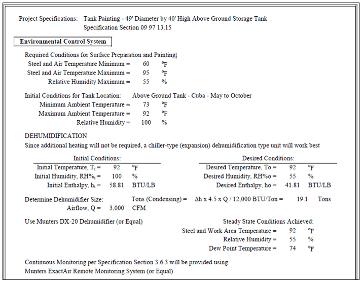
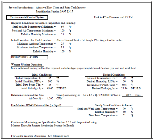
- Chiller Type Dehumidifiers – Calculate the change in enthalpy from the anticipated conditions to the desired conditions. Determine the dehumidifier size (in Tons) based on available equipment airflow rates from:
- Tons (Condensing) = (Dh) (4.5) (Q) / 12,000Btu/Ton where:
- Tons = Dehumidifier size from equipment manufacturer’s data sheets
- Dh = Change in Enthalpy from initial and desired Temperature and RH%
- Tons (Condensing) = (Dh) (4.5) (Q) / 12,000Btu/Ton where:
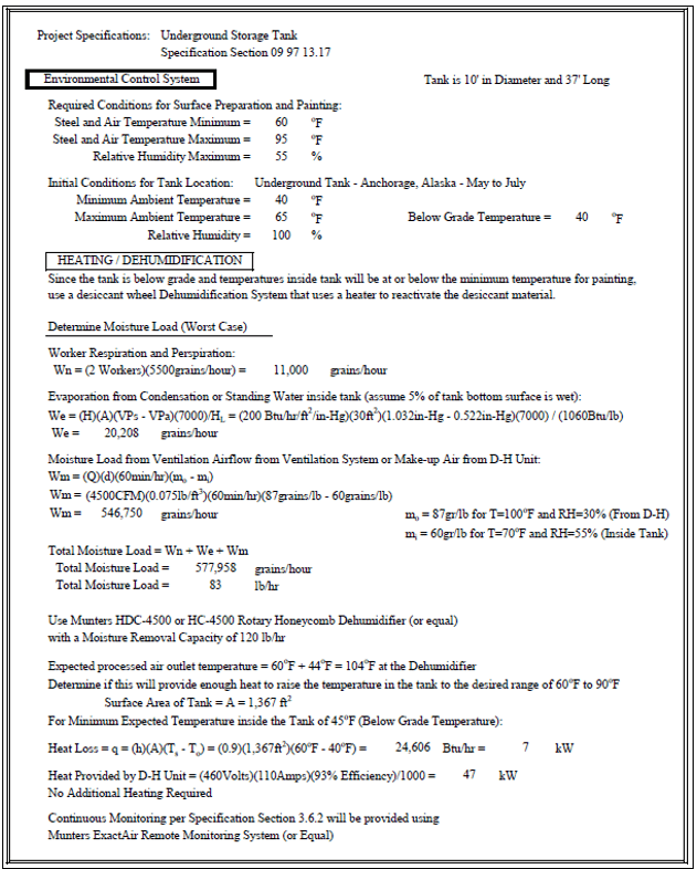
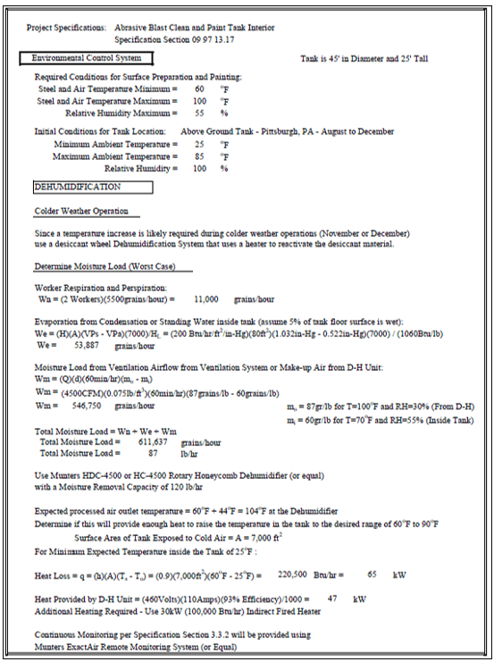
- Desiccant Wheel Type Dehumidification Systems – Calculate the moisture load (in grains of water per hour) from any source of moisture that can enter the tank. These generally include worker respiration and perspiration, condensation or standing water inside the tank, and moisture introduced from air infiltration or by the ventilation system’s make-up (inlet) airflow. Sum the moisture loads and size the equipment from moisture removal information provided by the equipment manufacturer. Determine if additional heating is required from the dehumidifier’s processed air outlet temperature using the heat losses shown above. Moisture loads can be calculated from the following:
- Worker Respiration and Perspiration:
- Wn = (Number of Workers) (5,500 gr / hr)
- Ventilation or Make-Up Airflow
- Wm = (Q) (d) (60 min./hr) (mo – mi) where:
- Q is dehumidifier’s airflow rate in cfm
- d is the air density in lb / ft3
- mo is the moisture level from the conditioned airflow in gr / lb
- mi is the moisture level inside the tank in gr / lb
- mi and mo are obtained from respective temperatures and RH%’s using the psychrometric chart
- Wm = (Q) (d) (60 min./hr) (mo – mi) where:
- Condensation or Standing Water Inside Tank
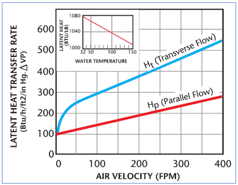
- We = (H) (A) (VPs – VPa) (7000) / HL where:
- H is the latent heat transfer rate in Btu/hr/ft2/in-Hg
- A is the wetted surface area in ft2
- VPs is the water vapor pressure of saturated air at the water temperature in inches of mercury (in-Hg)
- VPa is the water vapor pressure in the air above the surface in in-Hg
- 7000 is the grains of water vapor in one pound of water
- HL is the latent heat of vaporization at the water temperature in Btu / lb
- We = (H) (A) (VPs – VPa) (7000) / HL where:
- Worker Respiration and Perspiration:
Additional and more detailed information is available from various sources including thermodynamic and heat transfer textbooks, The American Society of Heating, Air Conditioning and Refrigerating Engineers (ASHRAE), and “The Dehumidification Handbook” by Munters Corporation. In fact, all of the figures in this article are from “The Dehumidification Handbook” and are used with full acknowledgement of Munters Corporation copyright.