Introduction – Precast concrete is cleaned and painted for both beautification and protection. Painting may involve the use of protective coatings, stains, or water repellents. For the materials to adhere and provide the desired service life, the quality of surface preparation and application must be assured. This can be accomplished by thoroughly inspecting each phase of the work.
Inspection Steps – Each step of the cleaning and painting processes for precast concrete should be monitored. Inspections include the following, which are also applicable to other types of concrete, such as cast-in-place and floors:
- Concrete Defects and Damage
- Surface Cleanliness
- Surface Profile
- Moisture Content
- Coating Mixing
- Ambient Conditions
- Wet Film Thickness
- Dry Film Thickness (non-destructive)
- Dry Film Thickness (destructive)
- Visual Appearance and Continuity
Concrete Defects and Damage – The concrete should be inspected for adequate cure, and for defects and damage that should be repaired prior to cleaning and painting as discussed Topic 1 of this series, “Inspection of the Precast/Prestressed Concrete Fabrication Process,” specifically the section on Post-Pour Inspection.
Surface Cleanliness – As discussed in Topic 2 of this series, “Preparation of Precast Concrete for Painting,” surface preparation may include one or more of the following. The methods of cleaning are described in the ASTM standards listed below as well as International Concrete Repair Institute (ICRI) ICRI Guideline 310.2, Selecting and Specifying Concrete Surface Preparation for Sealers, Coatings and Polymer Overlays. Guidance on the inspection of surface preparation can also be found in SSPC-SP13/NACE 6, Surface Preparation of Concrete.
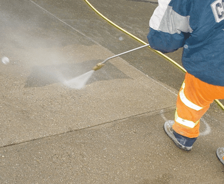
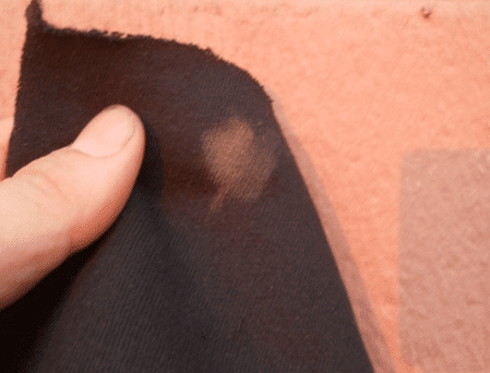
1 – Surface Cleaning. Surface cleaning removes grease, oil, dirt, dust, chalk, and other loose surface interference material. Cleaning methods include vacuum cleaning, air blast cleaning, water cleaning, detergent water cleaning and steam cleaning. These methods do not impart a profile on the surface. Before cleaning, the surfaces are visually inspected to identify the types of contaminants present. After cleaning, the surfaces are reinspected visually to verify removal. A dark cloth can also be rubbed across the surface to assess the amount of chalk or dust remaining, but project-specific acceptance criteria will have to be established because standards do not currently define how much chalk or dust, if any, is acceptable. If detergents are used in the cleaning process, inspections need to confirm that residual soap has been removed, typically by flushing with clean water. ICRI Guideline 310.2 and ASTM D4258, Surface Cleaning Concrete for Coating describe the cleaning methods.
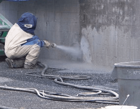
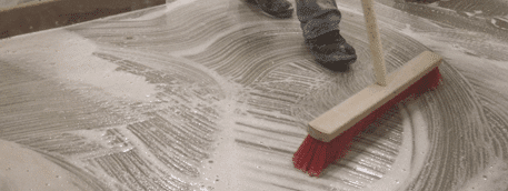
2- Mechanical Cleaning. Mechanical cleaning removes laitance, form-release agents, curing compounds, existing coatings, and weak concrete, and opens voids to provide a sound concrete surface, and in some cases a surface profile for coating adhesion. Methods that both clean and roughen surfaces include wet and dry abrasive blast cleaning, water jetting, and impact power tools. Methods that clean the surface but may not adequately roughen it, include power grinders and power wire brushes.
Pre-cleaning inspections are conducted to identify the materials requiring removal. If there are questions whether form-release agents or curing compounds are present, a few drops of acid can be dripped onto the surface. If the acid bubbles and foams, the concrete is bare. If it does not foam, a material may be on the surface, preventing the acid from making intimate contact with the bare concrete. If documentation on the material is not available, a test patch of the coating can be applied, and the tensile adhesion examined after adequate drying to determine if it can be overcoated. Adhesion can be tested according to ASTM D7234, Standard Test Method for Pull-Off Adhesion Strength of Coatings on Concrete Using Portable Pull-Off Adhesion Testers. When conducting the adhesion tests, the adhesion of the coating to the concrete should be greater than the strength of the concrete (i.e., forced detachment of the test stub should be within the concrete).
Methods of mechanical cleaning are described in ICRI Guideline 310.2 and ASTM D4259, Standard Practice for Abrading Concrete. SSPC is developing methods for the waterjet cleaning of concrete and has published three standards that describe different grades of dry abrasive blast cleaning of concrete and cementitious materials. The differences between the dry blast cleaning methods are primarily related to the amount of coating removed.
- SSPC-SP CAB 1 – Thorough Blast Cleaning (highest grade-removes all existing coating)
- SSPC-SP CAB 2 – Intermediate Blast Cleaning (removes most existing coating)
- SSPC-SP CAB 3 – Brush Blast Cleaning (lowest grade that removes loose coating)
Inspections include verification that the degree of cleaning and removal of existing coating required by the specified ASTM or SSPC methods are met and that the cleaning has not removed too much concrete. The surface profile must also be examined for compliance with the specification and manufacturer’s requirements (discussed in a later section). During cleaning, the performance of dust control measures should be assessed and when wet methods are used, containment and collection of water according to specification requirements should be verified.
3 – Chemical cleaning – acid etching. Chemical cleaning removes laitance and weak concrete and provides a surface profile. Before etching, the surface must be inspected to assure that material that can interfere with the acid making intimate contact with the concrete is not present (e.g., form release agents, curing compounds, coatings, grease, and oil). Dropping acid onto the surface as discussed under mechanical cleaning above, is suitable for this purpose. Acid etching is described in ICRI Guideline 310.2 and ASTM D4260, Standard Practice for Liquid and Gelled Acid Etching of Concrete. During etching, it is important to verify that the acid is bubbling and the surface is being etched. After cleaning, the surface needs to be examined for pH to assure that the acid has been completely flushed from the concrete. A test method for determining pH is found in ASTM D4262, Standard Test Method for pH of Chemically Cleaned or Etched Concrete Surfaces.
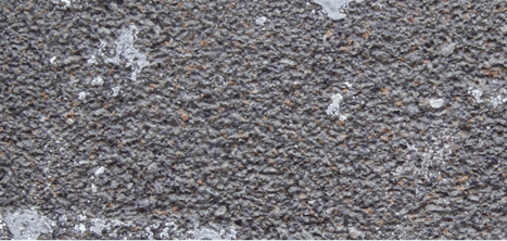
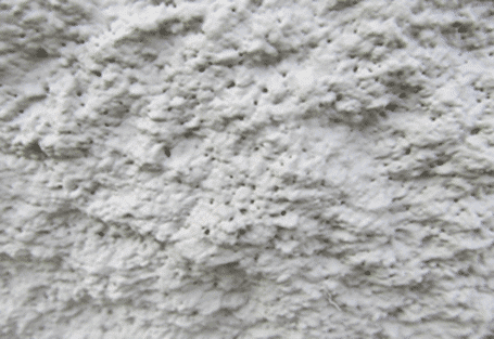
Surface Profile – A few methods are available to inspect the degree of surface roughening (surface profile) created by mechanical cleaning and acid etching:
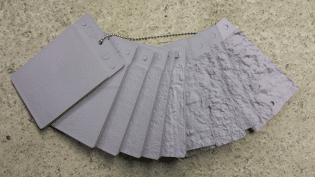
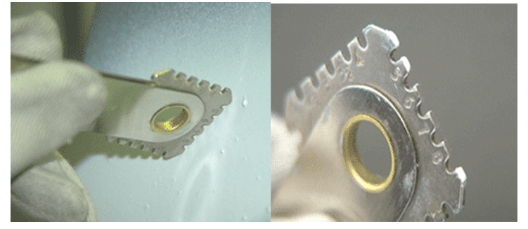
1- ICRI Guideline 310.2 describes the type of profile or surface roughness that is created by the various methods of cleaning. ICRI also provides concrete surface profile (CSP) coupons that are replicas of the profile, which can be compared to the surface to determine that an appropriate profile that has been created. The coupons range in texture from very smooth, typical of pressure washing (CSP1) to very rough, typical of jack-hammering (CSP 10):
-Detergent scrubbing – CSP1
-Low-pressure water cleaning – CSP1
-Grinding – CSP1-CSP2
-Acid etching – CSP1-CSP3
-Needle scaling – CSP2-CSP4
-Abrasive Blasting – CSP2-CSP7
-Shotblasting – CSP2-CSP9.
-High/ultra-high pressure water jetting – CSP3-CSP10.
-Scarifying – CSP4-CSP7
-Rotomilling – CSP6-CSP9.
-Scabbling – CSP7-CSP9.Handheld Concrete Breaker – CSP7-CSP10
-Handheld Concrete Breaker – CSP7-CSP10
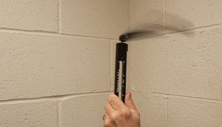
2- ASTM D8271, Standard Method for the Direct Measurement of Surface Profile of Prepared Concrete describes the use of a specialized depth micrometer to determine the roughness. The base of the instrument is approximately ¾ inch to 1 inch in diameter with a spring-loaded pointed probe the projects out of the center. The base is held firmly to the surface, resting on the tops of the peaks while the probe projects into the valleys. At each test location, 15 readings are taken, and the range and mean documented. The standard indicates that the number of locations to test on a surface should be adequate to characterize it but does not provide a specific number. Once all selected locations are tested, the range and mean of all locations is calculated.
3- ASTM D7682, Standard Test Method for Replication and Measurement of Concrete Surface Profiles Using Replica Putty describes a method for creating a permanent replica of the concrete surface that can be compared to the ICRI CSP coupons, measured with the depth micrometer, or measured under a laboratory microscope.
Moisture Content – Before applying coatings to the prepared concrete surface, the moisture content needs to be determined. Excessive moisture in the concrete can interfere with the proper formation and curing of the film, effect adhesion, and depending on the source, may lead to blistering and disbonding of the coating in service. A number of ASTM methods address moisture testing of floors and SSPC has developed a guideline based on many of those same standards for use on wall and ceilings; SSPC Technology Guide 23, Field Methods for the Determination of Moisture in Concrete and Masonry Walls and Ceilings, EIFS, and Stucco. The methods described in Guide 23 are:
1 –
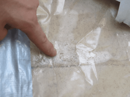
- Method 1 – Plastic Sheet Method. The perimeter of a sheet of polyethylene measuring approximately 18 inches x 18 inches is securely taped to the surface to create a complete seal and allowed to remain in place for minimum of 16 hours. Upon removal, the underside of the sheet and the surface of the concrete are visually (qualitatively) examined for evidence of moisture. The plastic sheet test is also described in D4263, Standard Test Method for Indicating Moisture in Concrete by the Plastic Sheet Method.
The plastic sheet test can also be combined with instrument methods described below to provide a quantitative assessment of any change in moisture content caused by the sheet. Moisture readings of the concrete before attaching the sheet are compared with readings taken immediately upon removal of the sheet. The combination of methods is described in Appendix X2.2 of ASTM F710, Preparing Concrete Floors to Receive Resilient Flooring.
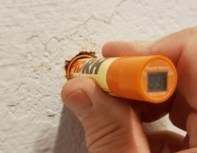
2- Method 2 – Electrical Impedance Moisture Meter. This instrument that utilizes the principles of electrical impedance to take non-destructive readings of moisture content to a nominal depth of 1 inch into the substrate. If coatings are present, they may need to be removed prior to testing. The results are provided in percent moisture, up to 6%. The electrical impedance meter is described in ASTM F2659, Standard Guide for Preliminary Evaluation of Comparative Moisture Condition of Concrete, Gypsum Cement and Other Floor Slabs and Screeds Using a Non-Destructive Electronic Moisture Meter.
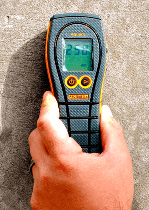
3- Method 3 – Radio Frequency Moisture Meter. This instrument utilizes radio frequency to non-destructively assess and monitor the relative moisture content in concrete to a depth of approximately 1 inch. It provides readings on a relative scale between 0 – 999, so the numbers do not represent a percentage of moisture. The instrument also uses a color code for the results:
-The green zone is from 0 to 145 units and signifies “safe air-dry conditions.”
-The yellow zone is between 146 and 230 units and signifies “moisture levels are higher than normal but not critical; further investigation is recommended.”
-The red zone is greater than 230 units and represents “excessive moisture levels.” Coatings do not have to be removed to obtain readings of the moisture content.
ASTM F2659 the describes electrical impedance (Method 2) includes a drawing of the radio frequency meter in Appendix X2, suggesting that radio frequency (this Method 3) may also be covered by the standard.
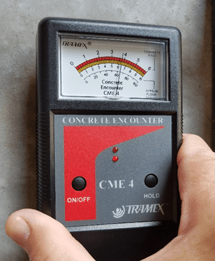
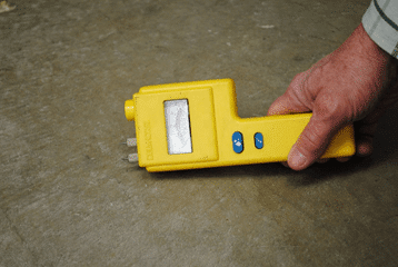
4- Method 4 – Electrical Conductivity (Resistance) Moisture Meter. This instrument utilizes conductivity to determine moisture content. Two contact pins on the end of the instrument are pushed against the surface to measure the conductivity (relative moisture content) of the concrete between the pins. Masonry nails can also be driven about ¼ inch into the concrete. The pins of the probe are touched to the heads of the nails to assess moisture content below the surface. Holes can also be drilled in the concrete to measure at lower depths, but the heat from drilling may influence the readings by artificially drying the test area. The results are provided on a relative scale from 0 to 100. One manufacturer indicates an approximate correlation between the scale reading and percent moisture content:
- Green Zone <85 units (<2% moisture content)
- Yellow Zone 85 to 95 units (2 to 4% moisture content)
- Red Zone >95 units (>4% moisture content)
This method is also described in Appendix X2.4 of ASTM F710, Preparing Concrete Floors to Receive Resilient Flooring.
5- Method 5 – Relative Humidity Probes. This a destructive technique that requires drilling a hole into the concrete about 5/8 inch in diameter to varying depths depending on the thickness of the concrete. A probe assembly or plastic tube or liner is installed in the hole and capped. After an equilibrium time of 24 hours has passed, the relative humidity within the concrete can be read according to the manufacturer’s instructions. This method is described in ASTM F2170, Standard Test Method for Determining Relative Humidity in Concrete Floor Slabs Using in situ Probes. Note that prior to the 2019 revision of the standard, the equilibration time was 72 hours rather than 24 hours.
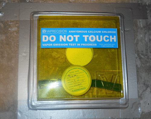
6- Calcium Chloride Test. ASTM F1869 Standard Test Method for Measuring Moisture Vapor Emission Rate of Concrete Subfloor Using Anhydrous Calcium Chloride is suitable only for floors, so it is not included in the SSPC-Guide 23 methods described above. This is a common test method for obtaining the MVER (moisture vapor emission rate) of the concrete. The results are provided in lb/1,000 ft2/24 h. The standard indicates that floors with a pre-existing floor covering should have a 20” X 20” square of the floor covering removed a minimum of 24 hours prior to testing. A dish of calcium chloride is placed on the floor and covered with a sealed dome. The test remains in place for 60 to 72 hours and calculations are made to determine the MVER based on an increase in the weight of the calcium chloride over the test period.
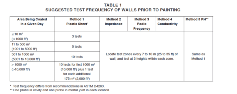
Moisture Testing Frequency. Table 1 below is from SSPC-Guide 23 showing the proposed frequency of moisture testing for the 5 methods.
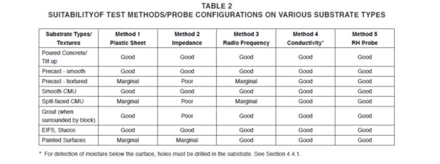
Suitability of the Methods for Various Concrete Types. Table 2 below from SSPC-Guide 23 compares the suitability of the 5 methods for use on various types of concrete.
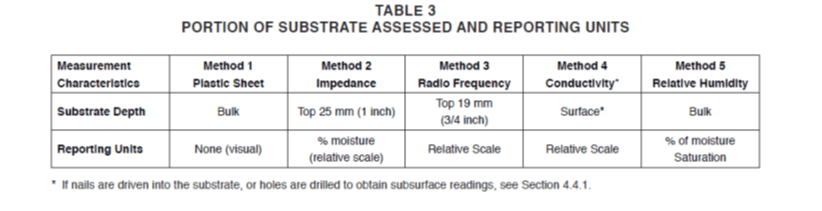
Depth of Moisture Measurement and Reporting Units. Table 3 from SSPC-Guide 23 describes the location within the concrete that the measurements by each method represent and the reporting units.
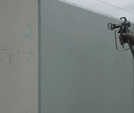
Coating Mixing and Application– Mixing and thinning of the coating should be examined to assure that the shelf life of the components has not expired and that the coatings are mixed and thinned according to the manufacturer’s instructions. If the mixing of partial kits is allowed, inspections should verify that the proper proportions are used. If the mixing of partial kits is prohibited, inspections should verify that only complete kits are mixed. This becomes a particular problem when a small amount of material is needed for touch up, but only 5-gallon kits are on the jobsite. Multi-component coatings must also be applied before the expiration of the pot life. If the coatings are applied using plural component equipment, the temperature of the components should be monitored as required by the manufacturer and the proper proportioning of the material confirmed. Application should be observed for proper technique and uniform coating application.
Ambient Conditions – The term “ambient conditions” encompasses air and surface temperatures, relative humidity, and dew point temperature. If the ambient conditions are outside of the limits of the specification or the coating manufacturer’s requirements, coating adhesion and film formation can be compromised, leading to reduced performance or failure. The measurements must be taken where the work is being performed because conditions can vary at different parts of a structure (e.g., in direct sunlight versus shade). The conditions are typically taken before painting begins and at 4 hours intervals thereafter. If the weather conditions are changing the frequency is increased.
The least expensive instrument for determining the air temperature, relative humidity, and dew point temperature is a sling or whirling psychrometer. A contact thermometer is used to determine the temperature of the surface. More expensive methods involve the use of digital or electronic psychrometers that contain a sensor that is exposed to the environment to determine air temperature, dew point temperature, and relative humidity. A separate probe is touched to the surface, or a non-contact infrared sensor is used to measure the surface temperature.
Wet Film Thickness – The measurement of the wet film thickness of the coating during application provides assurance that the proper amount of coating is being applied. Since the instruments available for non-destructively measuring the dry film thickness of the coating are limited, the wet film readings together with calculations of coverage based on the number of containers of paint used, often become the thickness measurement of record. The coating manufacturer can stipulate the wet film thickness to be applied to achieve the specified desired dry film thickness. The use of wet film thickness gages is described in ASTM D4414, Standard Practice for Measurement of Wet Film Thickness by Notch Gages.
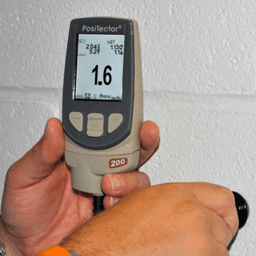
Dry Film Thickness (non-destructive) – The non-destructive measurement of the thickness of coatings applied to concrete substrates can be accomplished using ultrasonic gages that comply with ASTM D 6132, Standard Test Method for Nondestructive Measurement of Dry Film Thickness of Applied Organic Coatings Using an Ultrasonic Gage. The frequency of measurement and the acceptability of the measurements is addressed in SSPC-PA 9, Measurement of Dry Coating Thickness on Cementitious Substrates Using Ultrasonic Gages.
Dry Film Thickness (destructive) – The Tooke Gage is a destructive microscope technique (50x ocular) for the measurement of coatings applied to essentially any substrate. The instrument requires the use of specialized cutting tips to scribe through the coating at a known angle. By measuring the width of the scribe through the microscope, the depth or thickness of the coating can be determined since the cutting angle is fixed. Because the cutting angle must be constant to obtain an accurate reading, if the surface is irregular, the cutting angle may change during scribing, which would invalidate the results. But if the surface is smooth, accurate measurements can be obtained. The incision is about the width of a pencil line and approximately 1 inch in length. In addition to measuring total coating thickness, the instrument can be used to measure the thickness of individual coats if there is a color contrast between them. The Tooke Gage is used in accordance with ASTM D4138, Standard Practices for Measurement of Dry Film Thickness of Protective Coating Systems by Destructive, Cross Sectioning Means.
Visual Appearance and Continuity – Coating appearance, coverage and film continuity can be determined visually, paying particular attention to the presence of pinholes or lack of uniformity in voids or other depressions in the concrete. SSPC-PA 19, Standard for Visual Evaluation of Pinholes in a Concrete or Masonry Coating classifies pinholes on a substrate based on their frequency and provides a procedure for the uniform inspection of pinholes. Continuity of the film can also be determined according to ASTM D4787, Standard Practice for Continuity Verification of Liquid or Sheet Linings Applied to Concrete Substrates. A high voltage holiday detector is used to detect pinholes and other discontinuities in the applied film that reduce the effectiveness of the barrier created by the coating. For the detector to work, the concrete must be adequately conductive, and the coating being tested must be non-conductive. Inspections also include the identification of runs and sags, non-uniformity in gloss (flat spots), and other objectionable aesthetics.
Conclusion – Precast and other concrete is painted, sealed, or coated with water repellent to provide long-lasting protection and/or aesthetics. Satisfactory protection and aesthetics can be met provided the quality of both the surface preparation and application are controlled and verified through proper inspection. The types of inspections are similar to those performed for steel, but there are also some differences like concerns with moisture in the substrate and a greater reliance on wet film thickness measurements and coverage rates.
Other topics in this precast concrete series:
Topic 1 – Inspection of the Precast/Prestressed Concrete Fabrication Process
Topic 2 – Preparation of Precast Concrete for Painting
Topic 3 – Coating Systems for Precast Concrete
Topic 4 – Inspection of Surface Preparation and Coating Application
About the Author:

Kenneth Trimber is the president of KTA-Tator, Inc. He holds a Bachelor of Science degree from Indiana University of Pennsylvania, is an SSPC Protective Coatings Specialist, is certified at a Level III coating inspection capability in accordance with ANSI N45.2.6, is a NACE-certified Coating Inspector and an SSPC-C3 Competent Person.Trimber has more than 40 years of experience in the industrial painting field, is a past president of SSPC, chairman of the Committee on Surface Preparation, chairman of the Visual Standards Committee, chairman of the Task Group on Containment and chairman of the SSPC Commercial Coatings Committee. He is also past chairman of the ASTM D1 Committee on Paints and Related Coatings, Materials, and Applications.Trimber authored The Industrial Lead Paint Removal Handbook and co-authored Volume 2 of the handbook, Project Design. He was the recipient of the John D. Keane Award of Merit at the SSPC National Conference in 1990 and is a former technical editor of JPCL. In 2009 and 2012 he was named by JPCL as one of the 25 Top Thinkers in the coatings and linings industry and in 2015 was the recipient of the SSPC Honorary Life Member Award.