
Installation of a coating to a cathodically-protected pipeline or structure without first testing its resistance to cathodic disbondment can result in catastrophic failure of the coating. However, there are over twenty international standard test methods to evaluate a coating’s inherent resistance to cathodic disbondment; each with its own set of parameters and materials, which can be confusing. This article describes the value of cathodic protection (and when used in conjunction with protective coatings the compounded influence on corrosion prevention); discusses the importance of evaluating a coating’s resistance to cathodic disbondment prior to full-scale installation; highlights the key differences between four common ASTM International and NACE International test methods; and describes when one method may be selected over another.
The first step in understanding cathodic disbondment testing is appreciating the need for cathodic protection. Buried pipelines are almost always coated; however, once buried in earth it is difficult to visually determine whether the coating is performing adequately in such a severe environment, so a “back-up system” (cathodic protection) is often installed to protect the pipeline. Pipelines are typically quite long and the potential for corrosion is so great that passive cathodic protection (i.e., protecting with dissimilar metal, or sacrificial anode) will not provide adequate protection of the steel pipe should the coating become damaged or contain pinholes or holidays. Therefore, active cathodic protection imparted by an impressed current cathodic protection (ICCP) system is almost always used. This typically includes a DC power source, an AC powered transformer rectifier, and an anode ground bed. An ICCP system essentially interferes with the corrosion process and protects the pipeline or structure.
The widespread use of ICCP dictates that any coating intended for use on the pipe be tested for its resistance to cathodic disbondment. Cathodic disbondment is the loss of adhesion between the coating and metal substrate caused by the cathodic protection system. There are a variety of causes of cathodic disbondment of a coating system, including the environment to which the pipe is exposed, and the level of impressed current on the system. This article reviews the test parameters of three ASTM test methods and one NACE test method for evaluating a coating’s resistance to cathodic disbondment and provides guidance on how to select a given method.
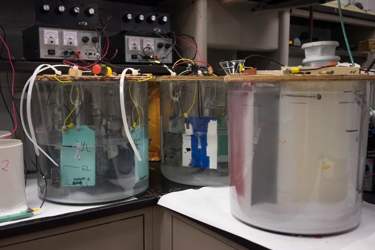
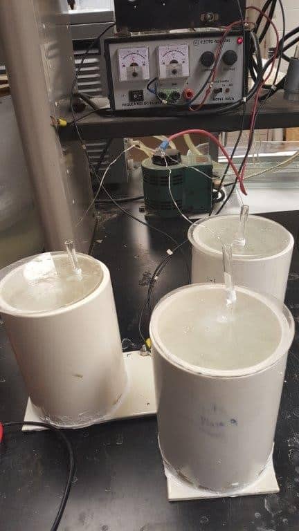
Test Method ASTM G8, “Standard Test Methods for Cathodic Disbonding of Pipeline Coatings” submerses or immerses the coated steel in a test solution maintained at room temperature. The test solution or electrolyte solution consists of potable tap water with 1 % by weight of each of the following technical grade salts: sodium chloride, sodium sulfate, and sodium carbonate. The test specimen that is submerged is a representative section of coated pipe with one end capped or sealed to allow the solution to only contact the outside of the pipe. An intentional holiday (in the area to be submersed) and reference holiday (in a non-immersed area) are created on the test specimen using a drill bit diameter no less than three times the coating thickness, but never less than ¼” in diameter. A magnesium anode is required for this test method. The potential between the test specimen and a reference electrode is maintained at approximately -1.5 V. The method is written for a 30-day test duration; however, test periods such as 60 or 90 days may be used. When the test is complete, evaluation of the coating’s resistance to cathodic disbondment involves cutting radial 45° incisions through the coating at the intentional and reference holidays and attempting to lift the coating away from the substrate. The area of disbonded coating is measured and recorded. This method is most appropriate when the test samples are coated pipe sections and elevated temperatures are not required.
Test Method ASTM G42, “Standard Test Method for Cathodic Disbonding of Pipeline Coatings Subjected to Elevated Temperatures” submerses or immerses the coated steel in a test solution maintained at elevated temperatures. The test specimen, intentional & reference holiday size, magnesium anode, and test solution are the same as that described for the ASTM G8 test method. The test vessel containing the test solution is maintained at 60 +/- 3°C on a hot plate with a magnetic stirring rod to circulate the solution, and the potential between the test specimen and a reference electrode is maintained at approximately -1.5 V. A 30- day test period is specified by the method; however, longer test periods may be specified. The evaluation of the coating at the end of test is the same as described for the ASTM G8 test method. This method is most appropriate when the test samples are coated pipe sections and an elevated temperature is required.
 Test Method ASTM G95, “Standard Test Method for Cathodic Disbondment Test of Pipeline Coatings (Attached Cell Method)” employs a test cell attached to the surface of the coating to hold the electrolyte solution. The method employs room temperature test conditions; however, a modified version of the method allows the test cell to be heated on a hot plate or in an oven. A coated test panel measuring at least 4” by 6” may be used. The test panel can be a flat panel or a curved section of pipe. The intentional and reference holidays are created with a 1/8” diameter drill bit. The attached cell can be a plastic or glass tube centered over the intentional holiday and sealed to the test surface with a waterproof sealer. The tube is a 4” diameter cylinder with a height to accommodate 5” of the electrolyte test solution. The test solution or electrolyte solution consists of distilled or deionized water with 3% by weight of technical grade sodium chloride. The anode for this test method is an impressed current anode consisting of a platinum wire in an immersion tube with a fritted disc. The potential between the test specimen and a reference electrode is maintained at approximately -3.0 V. The test duration is 90 days; the evaluation of the coating at the end of test is the same as described for the ASTM G8 test method. This method is most appropriate when the test samples are coated panels or curved panels.
NACE Test Method TM0115, “Cathodic Disbondment Test for Coated Steel Structures Under Cathodic Protection” can be performed using the immersed test specimens or attached cell methods. The testing can be performed on coated pipe, a test specimen cut from a section of coated pipe, or a flat coated steel plate. If the tube specimen is used, the end of the tube must be sealed (similar to that described in ASTM methods G8 and G42). Testing can be performed at room temperature or at elevated temperatures. One advantage to using this method is the test designer can select essentially any elevated temperature desired, provided it is representative of the actual environment. If the test temperature is between room temperature and 95°C, the method requires heating the solution using an immersion heater, a hot plate, heating mat, or oven. If the test temperature is above 95°C, the method requires heating using a circulation bath equipped with a heating element. The electrolyte for this method is 3% by weight sodium chloride in deionized or distilled water. The method has minimum dimensional requirements for the test specimens (4” x 4” for flat or curved panels for the attached cell method; and 4” x 6” x 1/8” flat panels or 2” diameter, 4” long pipe sections for the immersion method). The intentional and reference holidays are created using a ¼” diameter drill bit (unless otherwise specified). Any anode metal can be selected, provided it does not corrode in the electrolyte solution during the test period. Platinum titanium coated wire is suggested by the method. The potential between the test specimen and a reference electrode is maintained at approximately -1.38 V. The test duration is 28 days; other test durations may be specified. Evaluation of the test specimen must be performed within two hours of test completion, which involves making four radial cuts through the coating at the intentional and reference holidays and attempting to lift the coating away from the substrate. The amount of cathodic disbondment (CD) is calculated using the following equation:
CD = average disbondment diameter – (drilled holiday diameter / 2). For example, if the average diameter of disbondment is 0.5 inches and the drilled holiday diameter is 0.25 inches, the cathodic disbondment result would be 0.375.
This method allows for various solution temperatures and samples of both pipe sections and panels. It is most appropriate to use this method if the end user requires this method per a specification or wants to compare multiple test parameters by calculating the cathodic disbondment using the same formula.
In summary, there are several methods to choose from when evaluating a coating for its resistance to cathodic disbondment; each with its own set of parameters and test conditions. These test variations can produce different results on the same coating system. Therefore, it is important to select the method that is most appropriate. Selection of one method over another is based on:
- The test method specified by any contract documents;
- Inherent limitations of the coating system;
- Anticipated service conditions;
- Sample type, size and availability; and/or
- Previous testing, particularly when comparing the performance of competitive products.