Introduction
When applying coating system to structures such as bridges, tanks, and pipelines the main goal is to apply a continuous film to help prevent structural deterioration throughout the life of the structure. Unaddressed discontinuities can result in undercutting corrosion of the substrate, where the integrity of the structure could be prematurely compromised. This article will review the various methods used to examine coated surfaces for discontinuities (i.e., pinholes and holidays) and when each method is appropriate, and addresses potential issues with coating dielectric strength.
Definitions
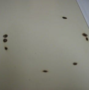
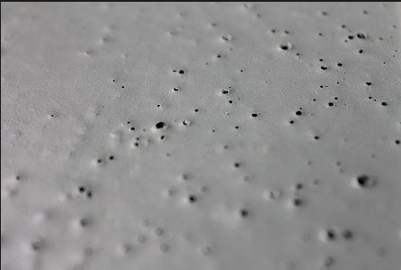 Holiday or pinhole detection is used to detect voids in the applied coating. Pinholes are tiny voids, or pin-sized holes that penetrate through a coating, but may or may not penetrate to the substrate. Pinholing can be caused by numerous factors, but essentially is the inability of the coating to thoroughly wet-out the surface. Holidays are skips or misses in a coating layer (like a holiday is a skip/miss in the work calendar) and are typically an error caused the applicator rather than the coating itself. Holidays are more prevalent for complex structures where it may be more difficult to access surfaces. Pinholes and holidays are of much greater concern when coating or lining performance cannot be easily observed, such as a buried pipe or the interior of a tank or vessel. These voids and misses can be detected by performing holiday detection, then repaired before the coating system is put into service. This inspection process is typically performed after application of the final coat of a system; performing holiday detection after each coat is not recommended as surface contamination may interfere with adhesion of subsequently applied coatings. Also, holiday detection is intended for use with new coatings applied to metal substrates. Its use on a coating previously exposed to an immersion condition can result in damage to the coating or produce erroneous detection of discontinuities due to permeation or moisture absorption of the coating. Deposits may also be present on the surface causing telegraphing (current traveling through a moisture path to a discontinuity, giving an erroneous indication) or current leakage across the surface of the coating due to contamination. Employing high voltage detection on previously exposed coatings can generate possible spark-through, which will damage an otherwise sound coating. Although a low voltage tester can be used without damaging the coating, it may also produce erroneous results.
Types of Holiday Detection
There are two main types of holiday detection; wet-sponge (low voltage) and spark (high voltage). Low voltage detection is typically used to inspect coatings that are less than 20 mils thick, while high voltage detection is used to inspect coatings greater than 20 mils thick. High voltage detection can be used on coatings between 10 and 20 mils in thickness provided the voltage is calculated correctly and can be precisely set on the detector.
 Wet-sponge detection consists of wand containing a metal end-clamp with a cellulose sponge which is saturated with tap water, a ground cable that is connected to an uncoated area on the structure, and a detection unit that will audibly alarm if any pinholes or holidays are detected. The voltage setting for coatings on steel is constant (67.5v) To use a low-voltage pinhole detector:
- Connect the wand to the detection unit using an insulated wire that connects the metal sponge clamp to the detector unit.
- Clamp the sponge to the end of the wand.
- Attach the ground wire to the detection then clamp the ground cable to the structure to complete the circuit. This clamp must be in contact with the uncoated substrate and not the coating (the coating will act as an insulator).
- Saturate the sponge with tap water, then wring the sponge to remove excess water that may cause surface telegraphing.
- Turn on the detector power.
- Move the wand in a consistent pattern across the coated surface at a rate not to exceed one lineal foot per second. If a pinhole or holiday is present the detector will produce an audible signal as the water from the sponge penetrates to the unprotected substrate, completing the circuit. The void is marked (i.e., with removable chalk) for repair.
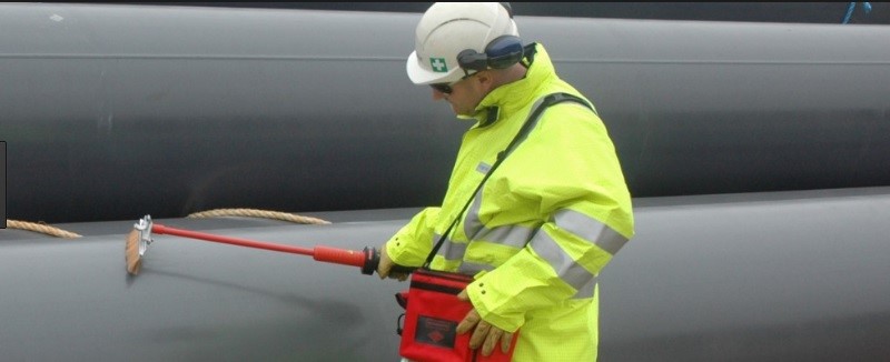 High voltage (spark) detection is similar, except metal bristles (pictured), Neoprene rubber or coil electrodes are employed instead of a sponge, and the voltage setting is adjustable, and must be calculated and entered onto the detector unit prior to use. A ground cable is attached to both the detector and the structure to complete the circuit. An audible alarm will be heard, and a spark will be visually observed as a holiday or pinhole is discovered.
For either method (low of high voltage), the substrate must be electrically conductive, and the coating must not be conductive. Coatings that contain conductive pigments (zinc, aluminum flake, etc.) cannot be tested using these methods.
Dielectric Strength Issues (Dielectric Strength)
 The dielectric strength of a material can be defined as the maximum electric pulse or field that a material can withstand without breakdown. Certain coatings are formulated to provide high dielectric breakdown resistance for use in high voltage environments and are tested according. Care should be taken to prevent exceeding the dielectric breakdown voltage when performing high voltage holiday detection. If too high a voltage is applied the coating system can be electrically burned and can adversely affecting the resin (binder) properties. Burning can also occur if the electrode is left stationary/sitting with no movement over a resulting holiday. While ASTM International and NACE International publish “suggested” voltage settings (based on a range of coating thickness) in their respective standards, it is highly recommended that the test voltage be calculated (using the procedures described in these same test methods) when considering high voltage holiday. These calculations are shown below. The manufacturer of the coating may also be a source for determining the proper voltage setting. The adage of “100-150 v/mil” may or may not be adequate. Also, while re-inspecting repair areas is recommended, re-inspection of the entire surface is not necessary nor recommended, especially for high voltage detection.
Test Methods
ASTM International, NACE International, and ISO have consensus standards that may be invoked by specification. ASTM standards include: D5162 “Standard Practice for Discontinuity (Holiday) Testing of Nonconductive Protective Coating on Metallic Substrates,” and G82 “Standard Test Methods for Holiday Detection in Pipeline Coatings.” Alternatively, NACE International SP0188 “Standard Practice – Discontinuity (Holiday) Testing of New Protective Coatings on Conductive Substrates” may be referenced, as well as ISO 29601 “Paints and Varnishes — Corrosion Protection by Protective Paint Systems — Assessment of Porosity in a Dry Film.” The underlying procedures and requirements of when to use each type of detector are the same, but the procedures vary when describing testing of coatings greater than 20 mils thick (spark testing); specifically, variations in adjusting required voltage for the different thicknesses. Tables are provided in each of the test methods that contain suggested inspection voltages. For example, ASTM D5162 provides a range of 19.7 to 307.1 mils (0.500 to 8.00 mm) coating thickness that is linear (2,700 to 30,000 volts). NACE SP0188 provides a range of 8 to 185 mils (0.200 to 4.7 mm) coating thickness that is linear to a suggested voltage testing range of 1,500 to 15,000 volts. The ASTM method provides an equation. ![]() In this equation, V is the test voltage in volts, and Tc is the measured coating thickness in mils or mm. M is a constant that is dependent on the coating thickness and units. An M constant of 3294 is used for coatings less than 1.00 mm, and an M constant of 7843 is used for coatings greater than 1.00 mm. When using mils as the units of thickness, an M constant of 525 is used for a coating thickness greater than 20 mils but less than 40.0 mils; an M constant of 1250 is used for coatings greater than 40.0 mils. The example shown is in mils.
In this equation, V is the test voltage in volts, and Tc is the measured coating thickness in mils or mm. M is a constant that is dependent on the coating thickness and units. An M constant of 3294 is used for coatings less than 1.00 mm, and an M constant of 7843 is used for coatings greater than 1.00 mm. When using mils as the units of thickness, an M constant of 525 is used for a coating thickness greater than 20 mils but less than 40.0 mils; an M constant of 1250 is used for coatings greater than 40.0 mils. The example shown is in mils.
Step 1: Calculate the square root of the coating thickness
Step 2: Multiply the square root of the coating thickness by a Constant: 525 for coatings < 40 mils and 1250 for coatings > 40 mils.
Example: Coating is 60 mils thick.
Step 1: Square root of 60 = 7.75
Step 2: 7.75 x 1250 = 9,688 volts (9.7kV)
Conclusion
Pinhole/holiday detection is invaluable for detecting discontinuities in the coating/lining that would otherwise create a pathway for oxygen and an electrolyte and cause deterioration of the underlying substrate. While pinholes and holidays may be visually evident, their detection is made simpler using low voltage (wet-sponge) or high voltage (spark testing) holiday detectors. Proper selection based on coating thickness, set-up (voltage setting for high voltage detection) and operation helps ensure proper testing without adversely affecting the dielectric insulating properties of the coating.
What coating DFT value should be used to set the voltage for a high voltage tester? the average, high or low of the test area. In my current situation we are testing Girth Weld coating on a pipeline so I have many individual spots to check but the same question could apply to a Tank lining.
Mark, the following comes from the author Dan Chasky:
Based on the literature and test methods, the average is typically used for calculation to set the detector to the proper voltage. This can be considered if the range of dry film thicknesses measured is somewhat tight. If there is a wide range of thicknesses measured, the detector should be set for each area appropriately, and mainly focused for the low end. This is to avoid burning of the coating, which can be common if the voltage is set to high for the area. Additionally, the coating manufacturer would want to be consulted, so to be informed what voltage range the coating itself can withstand if the dielectric strength is considered less than voltage calculated to be applied.