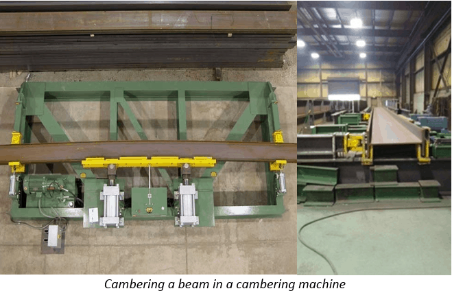
Steel beams used for bridge and highway structures are frequently curved to accommodate the design of a structure. This can be accomplished by cambering or sweeping. Cambering is the curving of a beam about the strong axis of the member, while, sweep applies to the curving of a member about the weaker axis. Cambering is typically performed by a steel fabricator after the member has been cut to length and punched or drilled. Beams that require square or parallel ends must be cut after cambering. Cambering steel in fabrication shops is usually achieved by applying a force on a steel member by mechanical means (Cold Bending) or applying truncated heat (Hot Bending). When camber is required in plate girders, the fabricator will typically cut the web plate to the desired camber profile prior to welding the flanges.
Cold cambering is the most common method used in fabrication shops to induce camber in a steel member, as it is a simpler and more cost-effective method than heat cambering. This method uses a mechanically induced force to achieve the desired curvature. The member (I – beam) is placed in a device called a cambering machine that is often built by the fabricator but is also commercially available. The cambering machine consists of two restrained pivots, one near each end of the beam and one or two hydraulic jacks near the middle of the beam. The jacks apply a force to induce camber into the member.
After placing the member at the restrained end pivots, the rams of the hydraulic jack or jacks are advanced to apply stress into the member past it’s yield point to produce a permanent deflection. When the rams are retracted, the residual deformation remains. The beam may need to be moved back and forth to actuate the jacking forces at different locations along the length of the beam to produce a uniform camber.
Depending on the capacity of the machine and the amount of camber required, this process may need to be repeated until the required deformation (camber) is attained. During this process adequate precautions should be taken to prevent over-stressing the beam and exceeding the yield strength of the member, which may result in buckling, excessive thinning of the convex flange, and cracks or tears in the member.
Correction of over-camber: It is important to never attempt to reduce the amount of camber in a member that has been over-cambered by immediately applying force to the beam in the opposite direction. If this action is taken, strain weakening may occur, and the steel strength may be affected. To correct over-camber in a cold cambered member, mild heat usually between 200°F and 550°F may be applied for a few minutes to accelerate molecular relaxation. The heat should be applied as evenly as possible in the most stretched and compressed areas of the beam. If the beam still exhibits an over- camber condition after mild heating, the application of heat in wedge-shaped segments can be used at the convex of the flange to provide the necessary adjustments.
There are limitations to the use of the cold cambering method. AASHTO/AWS D1.5 and owner specifications must be adhered to when proposing the method of bending.
Heat cambering is the alternate method available to steel fabrication shops. The heat cambering process is usually a more detailed, time-consuming, and labor-intensive method of inducing camber into a member. This process will require the use of a torch or multiple torches to apply heat to the flange and web of a beam using triangular heating patterns. The commonly used torch nozzle used in this application is a medium to large (approximately 1” to 1-1/2” diameter) rosebud type. Cutting torches cannot be used.
Heat cambering of rolled beams should be performed before the attachment of all detail material such as connection plates, bearing stiffeners, and gusset plates. Heat cambering of welded plate girders should be performed after the attachment of stiffeners and connection plates is complete. Heating of the member should be confined to specific heating patterns and should be conducted to bring the steel, within the planned pattern, to a temperature between 1,000°F and 1,150°F as rapidly as possible without overheating the steel.
Triangular heating patterns are spaced throughout the length of the member. The number of triangular shaped heating segments will vary depending on the length and size of the member and the amount of camber required. The apex of the heating triangle should be located in the web at a point not less than 75% of the depth of the member from the flange that will be concave after cambering. The heating will begin at the apex of the heating pattern and progress slowly with a total included angle not exceeding 20 degrees towards the base of the pattern and across the full width of the flange. Both surfaces of the flange must be heated simultaneously when the beam flange thickness is greater than 1-1/4″.
When heating begins, it should not be interrupted until the entire heating pattern is complete. The torch should not be returned to the apex of the heating triangle after heating has commenced. The progression is to move from the apex towards the flange – the base of the triangular heating pattern. Heating patterns should be centered on connection plate locations whenever possible. Temperature indicating crayons (temp sticks) are frequently used to verify heating temperatures; typical temp sticks of 600°F, 1,000°F, 1,100°F, 1,150°F and 1,200°F are used. Heat measurements must be made after the heating flame has been removed from the steel. The maximum temperature cannot exceed 1200°F.
Any heating that causes a portion of the steel to reach a temperature greater than 1,200°F is considered destructive heating and may be cause for rejection of the steel member. Steel subjected to destructive heating should be investigated, and acceptance or rejection is at the option of the Engineer or Owner.
After heating is complete, the steel cools naturally until it reaches a temperature of 600°F. Quenching with oil, water or cold air is prohibited. Further cooling with dry compressed air or fans moving ambient temperature air is permitted after the steel has naturally cooled to 600°F or lower.
Correction of Over-Camber: If a member has been over-cambered by the heat cambering process, the condition can be corrected by heating on the opposite side of the member; however, the heat is typically applied to a lesser extent than when initially inducing camber into the member. For example, if the heat was induced at four locations during the initial cambering of the member, the subsequent heat may only need to be applied to one or two locations on the opposite side to correct the over-camber condition.
In steel bridge fabrication heat cambering used to be the preferred method of inducing camber into a member. Mechanical cold cambering is now becoming the method of choice, especially with rolled beams. Whichever cambering process is employed, it is important that the processes are in accordance with the applicable code, specifications, and contract documents.


