Similar to steel, concrete is frequently roughened prior to application of a coating system to enhance the bond and help maintain adhesion of the applied coating when in service. According to Appendix A7 in the SSPC Joint Surface Preparation Standard SP 13/NACE No. 6, Surface Preparation of Concrete, the depth of surface profile required depends on the coating system to be used and the manufacturer’s recommendation. Factors that may influence the profile selected include: the tensile and shear strength of the concrete and the coating system; the adhesion of the coating system to the concrete; the internal stresses in the coating system created during application and cure (i.e., from shrinkage); the difference in the coefficient of thermal expansion between the coating and the concrete; the modulus or stress-relaxation properties of the coating system; the thermal and chemical exposure environment; and the coating thickness. It is apparent then that quantifying the surface profile depth in the specification and verifying it prior to coating application is of great importance.
The way in which the surface profile depth of concrete is quantified is different than the way the surface profile is measured on metal surfaces. Historically, the roughness of prepared concrete was visually (or tactilely) assessed by comparing it to sand paper of a specified grit size, using concrete surface profile (CSP) chips prepared by the International Concrete Repair Institute (ICRI), and/or by creating a mutually agreeable surface roughness standard[1]. All of these methods are considered qualitative, not quantitative. This article describes the standards and methods that can be used to determine the roughness of prepared concrete surfaces, including methods that are quantitative.
ICRI Guideline No. 310.2-1997 (formerly No. 03732),
Selecting and Specifying Concrete Surface Preparation for Sealers, Coatings, and Polymer Overlays
ICRI Guideline No. 310.2 addresses methods of surface preparation used on concrete. While the focus of the Guideline is on concrete floors, some of the methods are also suitable for use on vertical and overhead surfaces. The Guideline also includes 10 concrete surface profile (CSP) chips that are replicas of the type of profile (surface roughness) created by the various methods of surface preparation. The coupons range in texture from very smooth, typical of acid etching (CSP1) to very rough, typical of jackhammering (CSP 10).
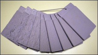
CSP1 (right) to CSP9 (left); CSP10 not shown
ASTM D7682, Test Method for Replication and Measurement of Concrete Surface Profiles Using Replica Putty
This method is designed to be used in conjunction with the ICRI CSP chips and provides the user with a permanent record of the concrete profile, as well as a method to indirectly quantify the surface profile from the replica putty disc. It describes two methods (A & B).
For Method A, replica putty (described below) is used to obtain a replica coupon of a roughened concrete surface, which is then visually compared to the ten ICRI CSP chips or to a project-specific standard.
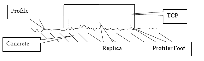
The replica putty may be used on vertical, horizontal or overhead surfaces. The concrete surface must be clean and dry. Plastic rings are used to measure equal parts of components A & B, which are then hand-mixed (gloved fingers/thumbs) for 35-40 seconds until a uniform color is achieved. The mix is then placed in the plastic cavity (TCP) as a mound in the center, then pushed firmly into the concrete surface for 3 to 5 seconds (see figure below), then allowed to remain undisturbed for 2-3 minutes (colder temperatures may require extra cure time for the epoxy putty). After verifying the putty is set (excess putty at perimeter of cavity can be tested with finger pressure) the cavity is removed from the surface, but the putty will remain on the surface. The putty disc is peeled from the surface and the disc retained as a permanent record.
For Method B in ASTM D7682, the replica putty coupon prepared for Method A is subsequently measured using a specially designed micrometer to obtain a quantitative measurement of surface profile depth. A minimum of ten micrometer measurements are obtained for each replica coupon in different locations, ensuring some measurements are taken in the bottoms of the valleys and some measurements are taken on the tops of the peaks. The lowest thickness measurement is subtracted from the highest thickness measurement to determine the profile range for each replica coupon.
Direct Measurement of Concrete Surface Profile
Recent technology now allows the user to quantitatively determine the profile directly from the prepared concrete surface, as opposed to obtaining the roughness indirectly from a replica disc or qualitatively by visual or tactile comparison to ICRI CSP chips. The procedure is similar to the depth micrometer described in Method B of ASTM D4417, although ASTM D4417 is for steel surfaces.
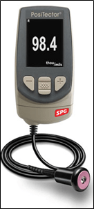
A depth micrometer fitted with a remote pointed probe machined at a 60° included angle with a nominal radius of 500 µm (20 mils) at the tip is required. The base of the probe should have a surface area diameter between 20 and 25 mm (0.8 to 1.0 inches). The base of the probe rests on the tops of the peaks of the surface profile while the spring-loaded tip, protruding from the probe face projects into the valleys using a minimum 75g force. The distance that the tip projects into the valley relative to the tops of the peaks is digitally displayed. Since surface profile depth of prepared concrete can be substantial, the depth micrometer must have a minimum upper range of 6 mm (250 mils). At the time this article was prepared (April 2019) a draft ASTM standard described the following procedure:
Step 1: Verify instrument accuracy prior to each period of use by measuring a metal shim of known thickness placed onto plate float glass usually supplied by the instrument manufacturer, then verify that the gage reads zero by placing its probe on a piece of plate float glass (zero plate). The gage manufacturer provides instructions for adjustments if the instrument does not read the shim or glass plate correctly.
Step 2: Hold the probe firmly against the prepared substrate to obtain readings of the roughened concrete without dragging the probe across the surface between readings or the spring-loaded tip may become worn, leading to false readings. Avoid bug holes and other surface irregularities that may generate false readings. Measure the profile at a sufficient number of locations to characterize the surface. Calculate the range and mean for each location and the range and mean of all the locations in micrometers (µm) or mils (0.001-in.).
Summary
The surface profile of prepared concrete surfaces can be assessed qualitatively using ICRI Concrete Surface Profile (CSP) chips (with or without a replica disc created using a proprietary epoxy putty), and can be assessed quantitatively by using a specially designed micrometer that measures the peaks valleys of the replica disc (indirect measurement of surface profile), or using a depth micrometer on the actual concrete surface (direct measurement of surface profile). There will likely be differences in the results when measured using each of these techniques, so it is important that only a single method be specified/used on a single project to avoid potential disputes.
[1] ASTM D6237-2009 (2015), Guide for Painting Inspectors (Concrete and Masonry Substrates)