
This is Part 2 of a 2-part series describing the instrumentation used to inspect the quality of cleaning and painting. Part 1 described the instruments used for determining the quality of cleaning and paint. Part 2 addresses moisture detection. The moisture content of the concrete should be determined prior to painting. In the author’s experience, moisture within the substrate is a leading cause of coating failures on concrete. If the moisture is elevated, the source(s) should be identified and corrected before paint is applied. One the paint is applied, the continuity of the film should also be determined to confirm that flaws are not present in the applied coating that will allow air, and therefore moisture, to pass through the film, to subsequently dampen the substrate in the future.
A number of instruments and techniques are used to determine the moisture content of concrete substrates. Some (calcium chloride and RH probes) are primarily used on floors, while others (radio frequency, conductivity, electrical impedance, and plastic sheet) are suitable for any concrete substrate. An instrument used to determine that the coating is free of flaws that could lead to future wetting of the substrate is based on creating a pressure differential across the film to locate detects. All of the aforementioned tests and methods are described in this article.
Radio Frequency
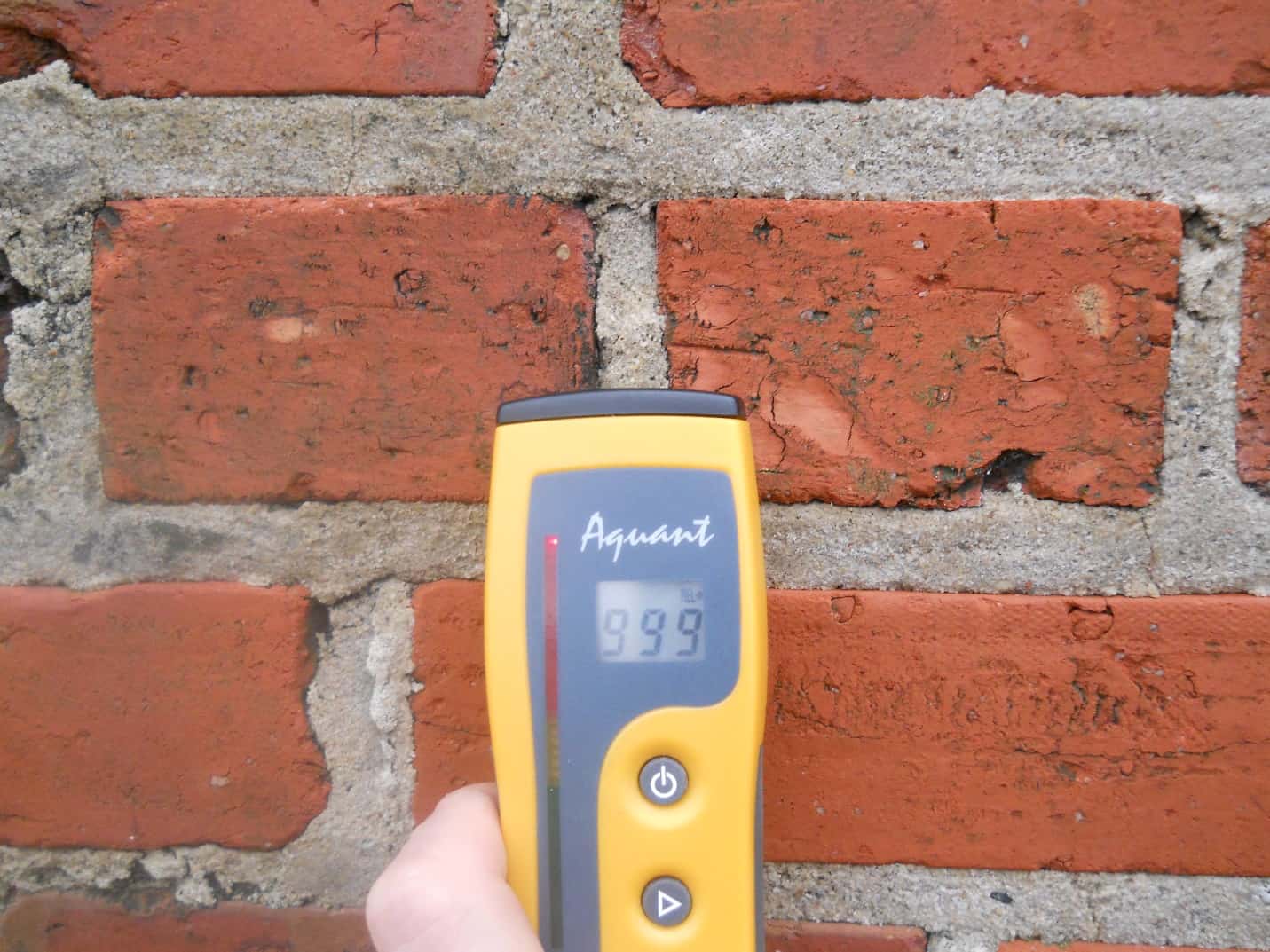
The instrument described below utilizes radio frequency to assess and monitor the relative moisture content in concrete to a depth of ~ 1 inch. It provides readings on a relative scale between 0 – 999. The instrument displays results using both a color and a number. The green zone is from 0 to 145 units and signifies “safe air-dry conditions.” The yellow zone is between 146 and 230 units and signifies “moisture levels are higher than normal but not critical; further investigation is recommended.” The red zone is greater than 230 units and represents “excessive moisture levels.” See Photo 1.
Step 1 – Press the top button to turn the gage on and set the instrument to the prevailing weather conditions by pressing the lower “arrow” button for 3 seconds until the word “nul” shows. Nul will flash and when it disappears, the gage is ready for use under the current ambient conditions. If the instrument is being used on the exterior of a building, but you move to the interior, repeat this step when inside the building.
Step 2 – Hold the instrument (gage) flush to the concrete substrate with your fingers on the black plastic perimeter of the gage body. Do not allow your fingers to extend to the front of the gage beyond the black. The gage requires a firm 2-point contact to take a reading (the front nose of the gage and the protruding rounded base).
Step 3 – The instrument will give an audible signal when the reading stabilizes. Record the value from the digital display and note the color.
Electrical Resistance (Conductivity)
The instrument described below utilizes conductivity to determine moisture content. Two contact pins on the end of the instrument are pushed against the surface to measure the conductivity (relative moisture content) of the material between the pins. Masonry nails can also be driven into the surface about ¼ inch in depth to assess moisture content below the surface. The pins of the probe are touched to the heads of the nails.
Depending on the model, the instrument uses either an analog or digital scale. When using the analog instrument, readings can be taken from 2 scales. The scale for concrete is a relative scale from 0 to 100. See Photo 2.
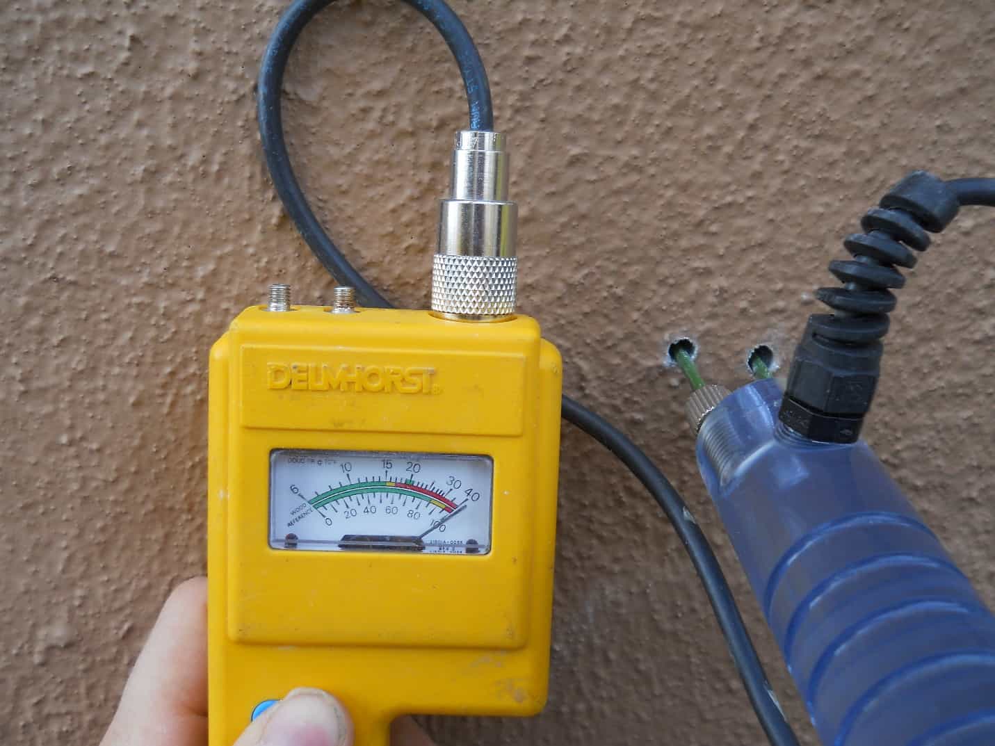
Caution: When using the analog scale, many users inadvertently record readings from the “wood” scale which is a percentage. The percentage on the wood scale has no relationship to the moisture in concrete. The concrete scale can be interpreted as follows:
- Green <85 units (<2% moisture content)
- Yellow 85 to 95 units (2% to 4% moisture content)
- Red >95 units (>4% moisture content)
Step 1 – Turn the instrument on and check the calibration. For the analog instrument, press the button with the “√.” The needle should read 20 on the wood scale. For the digital model, press the Read Button (a moisture droplet insignia is printed on the button) and the Calibration (check) button simultaneously. It should display 12% (+/- 0.2). If the readings are not in the above ranges, change the battery.
Step 2 – For the digital instrument, press the scale button (*) and set the scale to “2” for concrete. For the analog instrument, nothing needs to be set, but make sure you are using the “reference” scale for concrete. A very common mistake is to read the “wood” scale, which will provide incorrect results.
Step 3 – Press the probe firmly against the surface, making certain that both pins are in intimate contact with the concrete.
Step 4 – For the analog instrument, press the button with the “moisture droplet” insignia and record the number from the “reference” scale. For the digital instrument, push the “moisture droplet” button and a digital reading will be displayed.
Step 5 – To obtain readings below the surface, drive concrete nails into the surface and hold the pins of the instrument probe on the nail heads (1 pin on each nail head).
Electrical Impedance
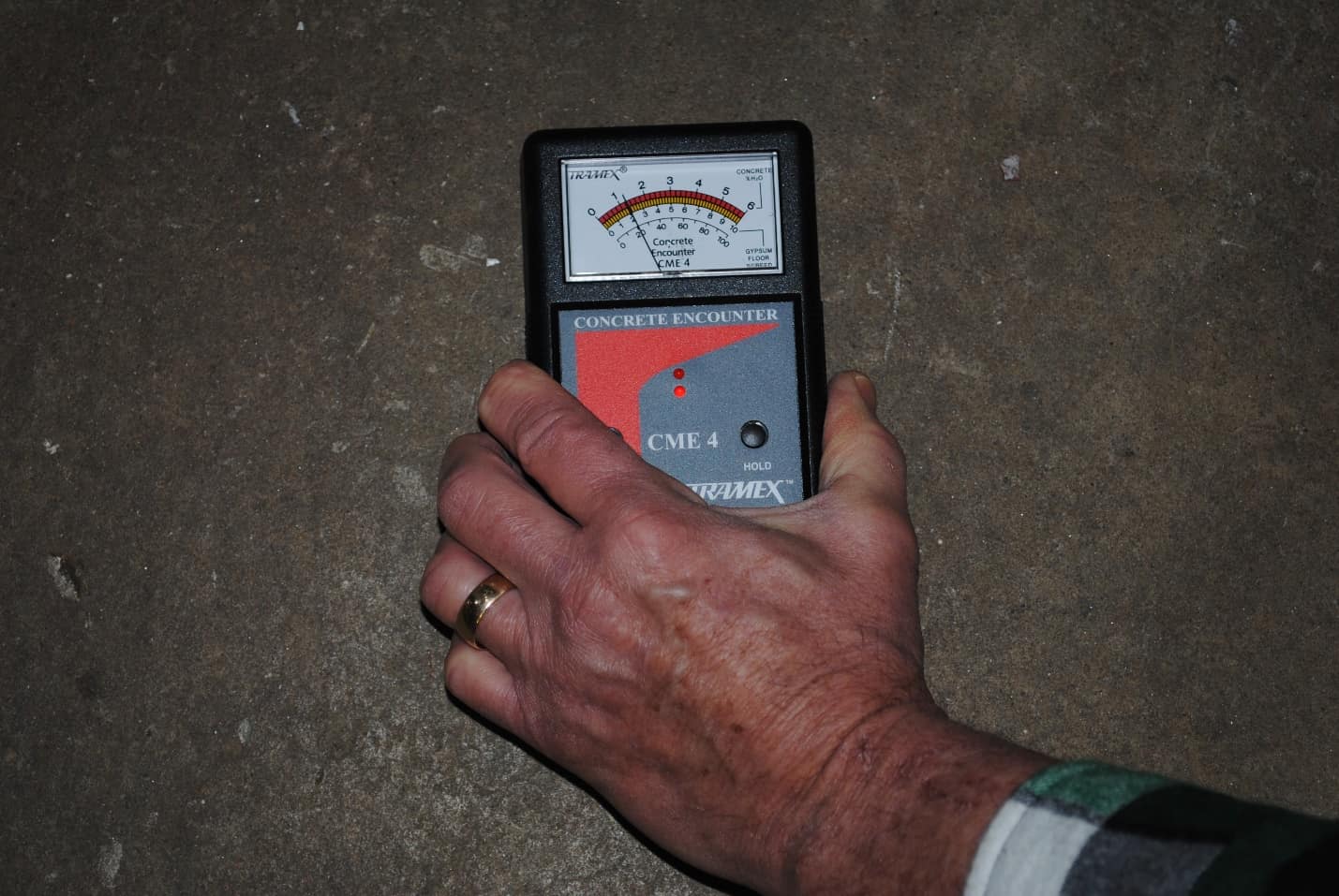
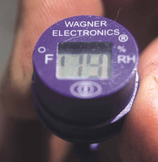
The instrument described below utilizes electrical impedance to determine moisture content to a depth of ~1 inch. The electrical impedance is measured by creating a low frequency electrical field between the electrodes on the bottom of the unit. The moisture readings are displayed on a moving coil meter ranging from 0% to 6%. See Photo 3.
Step 1 – Press the on/off button to power up the instrument. The lower LED will flash. If both lights flash, replace the battery.
Step 2 –Hold the instrument flush to the concrete substrate. All of the spring loaded feet of the gage should be in full contact with the surface.
Step 3 – Read the percentage from the top 0 to 6% scale.
Plastic Sheet Test
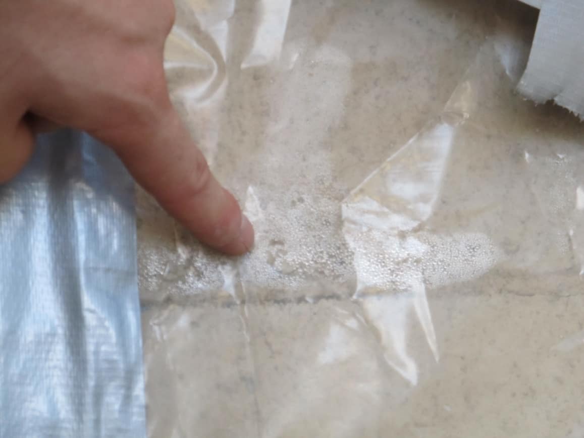
The plastic sheet test is a qualitative method for determining the presence of moisture within the substrate. The test is addressed in ASTM D4263-83 (2012), Standard Test Method for Indicating Moisture in Concrete by the Plastic Sheet Method.
Step 1 – Cut a sheet of clear plastic approximately 18 in x 18 in size. Note that when used on concrete block (CMU), in order to get a good seal with tape in Step 2, it may be necessary to cut the plastic in the shape of the block(s) so that the outside perimeter falls onto mortar joints.
Step 2 – Firmly tape the perimeter of the plastic to the surface to create a continuous seal.
Step 3 – Allow the plastic to remain in place for a minimum of 16 hours.
Step 4 – At the end of the exposure time, examine the underside of the sheet and surface of the concrete for the presence of moisture. See Photo 4.
Calcium Chloride
This method is addressed in ASTM F1869-11, Standard Test Method for Measuring Moisture Vapor Emission Rate of Concrete Subfloor Using Anhydrous Calcium Chloride. The test requires exposing the concrete slab to anhydrous calcium chloride for a given length of time (Photo 5). The results are expressed as the moisture vapor emission rate (MVER), reported in pounds of moisture over a 1,000 square foot area during a 24-hour period.
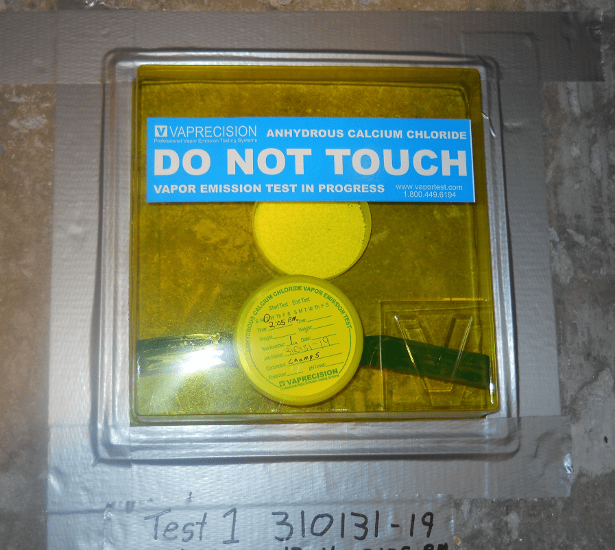
The testing should be conducted at the same temperature and humidity that is expected during normal use. If this is not possible, the ambient conditions should be controlled to 75°F ± 10°F and 50% ± 10 % relative humidity for 48 hours prior to testing and during the test. An exception to testing at the expected service temperature/relative humidity involves floors that operate at temperature or humidity extremes (e.g., cold storage rooms). In these cases, the temperature/humidity criteria listed above should be maintained.
ASTM F1869 recommends a test frequency of 3 locations for the first 1,000 square feet, with an additional test location for each 1,000 square feet of floor area, or fraction thereof.
Step 1 – Lightly abrade a 20 in x 20 section of the concrete surface by grinding to produce a slight profile equal to ICRI CSP-1 to CSP-2 and to remove the thin layer of finished concrete, but not exposing large aggregate. If floor coverings or coatings were removed in the test area, the concrete must be exposed for 24 hours after grinding before initiating the test. If the concrete was not covered, or the coverings have been removed for more than 30 days, testing can begin immediately after grinding and clean up. The 24 hour waiting period is not required.
Step 2 – Remove all dust from the surface.
Step 3 – Weigh the sealed plastic container containing the anhydrous calcium chloride to the nearest 0.1 gram.
Step 4 – Place the container on the prepared concrete and carefully remove the tape and lid to expose the calcium chloride. Store the lid and tape for reuse when the test is complete.
Step 5 – Cover the container of calcium chloride with the transparent dome provided by the manufacturer. Press firmly to complete seal the gasket material to the concrete around the perimeter of the dome.
Step 6 – Allow the container to remain in place for no less than 60 hours, nor longer than 72 hours.
Step 7 – At the completion of the test period, place the lid on the container and firmly tape it in place with the same tape that was originally on the container.
Step 8 – Reweigh the container using the same scale used for the pre-test weighing.
Step 9 – Insert the pre and post weights and exposure time into the formula supplied with the test kit to determine the MVER, reported as pounds/1000 sq ft/24 hours.
Relative Humidity
This method is addressed in ASTM F2170-11, Standard Test Method for Determining Relative Humidity in Concrete Floor Slabs Using in situ Probes. This is a destructive test that requires drilling small holes in the slab, inserting hollow sleeves, and after a given waiting period, inserting probes into the sleeves to determine the relative humidity. The results are directly displayed as relative humidity; no conversions are needed (see Photo 6).
The slab should be at service temperature and the occupied air space above the floor should be at the service temperature and relative humidity for at least 48 hours prior to testing. The hole depth for the probes is based on a percentage of the slab thickness. If the slab is drying from the top only (e.g., slab on grade, or slab on a metal deck), the hole is drilled to a depth of 40% of the total thickness of the slab. For a 4 inch thick slab, the hole depth is approximately 1.5 inches. If the slab dries from both the top and bottom (e.g., elevated reinforced slab not on a metal deck), the hole is drilled to a depth of 20% of the total thickness of the slab. For a 4 inch thick slab, the hole depth is approximately 0.75 inches.
ASTM F2170 recommends a test frequency of 3 locations for the first 1,000 square feet, with an additional location for each 1,000 square feet of floor area, or fraction thereof. For on-grade and below-grade slabs, one location is to be within 3 feet of each exterior wall.
Step 1 – Drill the hole using a hammer drill and drill bit (dry). The diameter of the hole is established by the manufacturer.
Step 2 – Vacuum the dust from the hole, use a round wire brush sized to the hole diameter to thoroughly scour the hole to remove any loose material and vacuum again.
Step 3 – Some manufacturers require the insertion of a sleeve in the hole or a sensor. In both cases, the hole containing the sleeve or sensor is capped and allowed to remain undisturbed for 72 hours prior to testing to achieve equilibrium.
Step 4 – Follow the manufacturer’s instructions to obtain a reading. First allow the instrument to reach equilibrium in the test environment. Depending on the instrument being used a probe attached to an RH gage is inserted into the sleeved hole to obtain a reading, or a reader is attached to the pre-installed sensor to obtain a reading.
Paint Film Continuity – Air Leak Detector
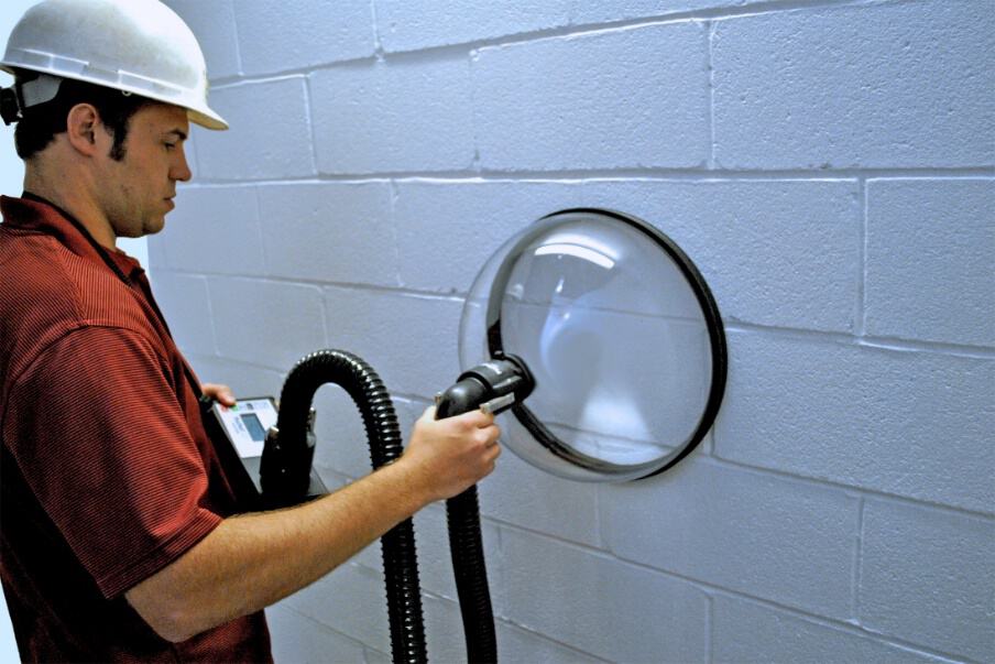
ASTM E1186, Air Leakage Site Detection in Building Envelopes and Air Barrier Systems, describes a number of methods that are used to determine whether air barriers installed on buildings are effective. Some of the methods test the entire enclosure, while others test specific locations, such as coatings, joints, penetrations, and junctions. The instrument described below (Photo 7) is used to test specific locations on a structure to determine if the surface is properly sealed. While the instrument can be used during commissioning, it should be used during construction to confirm that the installation practices are creating an effective non-leaking air barrier. Random areas are tested to confirm that the paint application techniques are suitable for creating a continuous film.
Step 1 – Adjust the leak detector to the specified pressure differential limit and rate of depressurization. The common test parameters are 500Pa and 25 Pa/sec, respectively.
Step 2 – Clean the area around the detail to be tested.
Step 3 – Apply a specially formulated liquid test solution to the surface.
Step 4 – Place the test chamber over the test area.
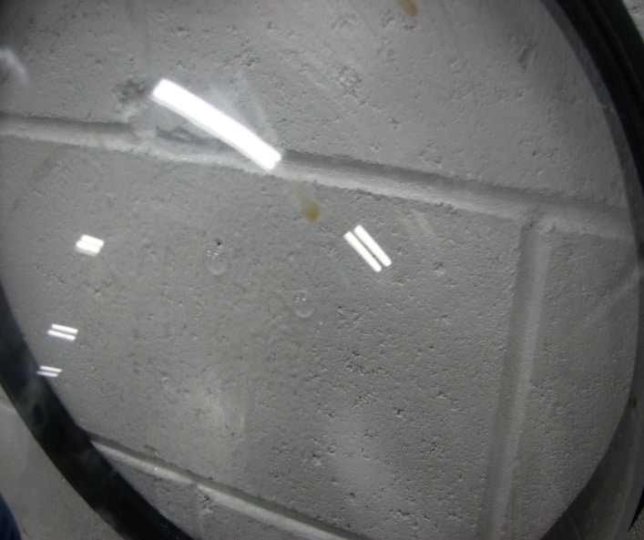
Step 5 – Start the instrument and carefully observe the test area for the formation of bubbles. Bubbles indicate the presence of a leak and poor film continuity. If not bubbles are present, the test area is free of air leaks.
Step 6 – Clean the test area to remove the test solution.
Conclusion
While inspections to confirm the quality of surface preparation and paint application are the most visible and obvious part of the painting process, an equally important aspect of the process involves the detection of moisture within the substrate and continuity of the film. These aspects are often “invisible” and therefore not fully appreciated. Common methods for detecting moisture and film continuity have been discussed in this article. See Part 1 of this Series for a discussion of instruments used for cleaning and painting.
ABOUT THE AUTHOR

like this article? you might also enjoy…
https://ktauniversity.com/tools-and-techniques-for-measuring-coating-quality/
https://ktauniversity.com/industry-standards-are-you-current/
https://ktauniversity.com/measuring-coating-thickness-according-to-sspc-pa2-updated-2015/