When conducting a coating failure investigation, the investigator’s first inquiries should be “What was supposed to be done,” and “Does it make sense?” The answers to these questions are typically revealed in the specification for the project. However, in this “Case from the F-Files,” there was very little information in the specification to guide the investigation; and there was little information available from the application, because in-process inspection was not performed. These circumstances made the failure much more challenging to resolve, and the resolution was based solely on the results of the field and laboratory investigations, along with the experience of the investigator.
The Structure
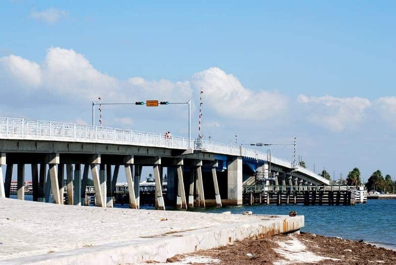
The structure, a drawbridge, carries vehicular traffic over an intercoastal waterway (Fig.1). The bridge consisted of a 24-foot closed vertical clearance with 91 feet of horizontal clearance in the center span. The structure raises and lowers on demand, 24 hours a day with no restrictions. The bridge deck and walkways on both sides consisted of open grating. Railings, guardrail, and curbing on the lift span sections were constructed of steel. In addition, there was a pedestrianwalkway underneath and parallel to the bridge on the mainland side of the structure. The appearance of the bridge indicated that it had been painted after the original coating application. The new coatings were, as reported by persons on the job site, applied to reduce the onset of corrosion and to improve aesthetics.
The coating history of the structure was essentially unknown. Widespread corrosion was evident, despite the fact that the structure was repainted approximately three years earlier. There were no records identifying the degree of surface preparation or the type of coating system most recently applied or identifying the original coating system.
The Field Investigation
The field investigation included visual examination of failing and non-failing areas, nondestructive and destructive coating thickness measurements, adhesion assessments, and sample collection for laboratory analysis.
Visual Examination
The coating system contained a blue finish coat, much of which was faded and chalked in areas exposed to sunlight, either directly or reflected off of the water. Approximately 3% of the steel surfaces contained corrosion, predominantly on edges, connections, and corners. Although the coating history was not revealed by records, maintenance painting had been performed in the past, as evidenced by surfaces where the older coating layers were missing beneath the most recent applications. Some sections of the structure contained pitting corrosion beneath intact coatings.
Although the corrosion was localized, it was consistently present on nearly all similar connections. A prime example of this was where lift section floor stringers were attached to floor beams (Fig. 2). All such connections had some corrosion evident. Careful examination of the area (as seen in Fig. 2) also showed the presence of rust on the sides of rivet heads and bolted connections (nuts) near the corners of the connection plate. The corrosion brought into question the thoroughness of surface cleaning and coating operations during the most recent maintenance painting activities.
Figure 3 depicts the presence of corrosion at bearings supporting flanking span girders. These areas also show evidence of previous pitting corrosion on the girder. The flanking span girders also exhibited corrosion on flange edges and spot corrosion on the webs. The exposed bolted connections for the concrete diaphragms also exhibited corrosion. Figure 4 illustrates the condition of the east flanking span girders and the lift span section counterweight. Edge corrosion was present on the counterweight and girders, and the color of the finish coat (light blue) indicated color fading due to weathering.
Although the amount of rusting depicted in Figs. 2–4 appeared relatively minor, the distribution was widespread and affected all of the steel members to some degree. Sites exhibiting the most advanced corrosion (Fig. 5) were difficult access areas that were evidently not fully cleaned during the most recent maintenance painting.
Physical Assessment of Coating Condition and Sample Acquisition
The physical condition of the existing coating system was evaluated by measurement of coating thickness (total and individual layers) and adhesion. The condition of the substrate was also examined. A representative test area is shown in Fig. 6. Destructive coating thickness measurements were obtained in accordance with ASTM D 4138, “Test Method for Measurement of Dry Film Thickness of Protective Coating Systems by Destructive Means (Tooke Gage).” Testing was performed to identify the number of layers present and the thicknesses of the individual layers. Table 1 shows the results. Measurements were also obtained by non-destructive means in accordance with ASTM D 7091, “Nondestructive Measurement of Dry Film Thickness of Nonmagnetic Coatings Applied to Ferrous Metals and Nonmagnetic, Nonconductive Coatings Applied to Non-Ferrous Metals.” Table 2 shows the data.
Table 1 – Individual Layer Thickness Values (ASTM D 4138)
| Layer | Color | Flanking Span Girder | Lift Span Floor Beam | Lift Span Stringer | Counterweight Panel |
| Topcoat | Blue | 2 – 3 mils | 2.5 – 4 mils | 1.5 – 3 mils | 2 – 3 mils |
| Intermediate | Dark Gray | 7 – 10 mils | 11 – 13 mils | 10 – 12.5 mils | 7 – 11 mils |
| Intermediate | Blue | 1 – 2 mils | 1.5 – 2.5 mils | 2 – 3 mils | 4 – 6 mils |
| Primer | Light Gray | 2 – 3 mils | 2 – 2.5 mils | 1 – 2.5 mils | 1 – 2.5 mils |
Table 2- Total Coating Thickness on Steel Spans (ASTM D 7091)
| Area Description | Average Thickness (mils) | ThicknessRange (mils) |
| Flanking Span Girders | 21.0 | 13.0 – 34.0 |
| Lift Span Girders | 20.5 | 15.7 – 27.3 |
| Lift Span Floor Beams | 23.7 | 17.3 – 35.3 |
| Lift Span Stringers | 24.2 | 16.2 – 36.0 |
| Lift Span Outriggers | 22.4 | 17.4 – 29.8 |
| Counterweight Panels | 23.6 | 17.0 – 31.9 |
| Miscellaneous Items | 21.3 | 10.7 – 44.4 |
| Sidewalk Railing | 20.0 | 10.9 – 32.2 |
| Deck Curb | 22.3 | 16.5 – 27.0 |
Coating adhesion was measured according to method A (X-cut) and B (cross-cut) of ASTM D 3359, “Standard Test Methods for Measuring Adhesion by Tape Test,” and according to ASTM D 6677, “Standard Test Method for Evaluating Adhesion by Knife.” The scale for rating the tape adhesion ranges from 5 (excellent) to 0 (poor); the scale for rating the knife adhesion ranges from 10 (excellent) to 0 (poor). The spacing between the incisions was 5 mm for method B. Table 3 shows the results of the adhesion testing.
Table 3- Results of Adhesion Tests on Visually Intact Coating
| Test Procedure | Flanking Span Girder | Lift Span Girder | Lift SpanFloor Beam | Counterweight Panel |
| ASTM D 3359 (X-Cut) | 1A | 4A | 2A | 4A |
| ASTM D 3359 (Cross-Cut) | 0B | 0B | 0B | 0B |
| ASTM D 6677 (Knife) | 6 | 6 | 6 | 8 |
The gray primer remained on the substrate at the adhesion test sites. The weak plane was the interface of the gray primer and blue intermediate coat. In some cases, the gray primer split cohesively. Cross-cut adhesion was performed to further characterize the adhesion/cohesion properties of the coating system. Typically, this method is limited to use on coating films less than 5 mils’ thick.
The steel substrate was examined where destructive testing and sample collection were performed. The substrate beneath intact coating was free of corrosion and mill scale. The substrate was too dark to determine the degree of abrasive blast cleaning that may have been performed.
Seven samples were collected from the bridge for subsequent laboratory analysis. The samples included both coating chips and corrosion product.
Laboratory Investigation
The laboratory investigation included microscopic examination of coating samples to determine the number of layers and confirm the field coating thickness data, infrared spectroscopy for coating resin identification, and quantitative chloride analysis of the corrosion products collected.
Microscopic Examination
Microscopic examination was conducted using a digital microscope. Individual coating layers were observed in cross-section. The examination confirmed that four coating layers were present on each of the samples examined. The thickness of the original coating was relatively low, with the original primer ranging from 1 to 2 mils and the original topcoat ranging from 1 to 6 mils. The most recent coating system was comparatively thicker, with the new primer ranging from 10 to 15 mils and the new topcoat ranging from 2 to 6 mils. The heavy thickness of the primer may have been specified to provide increased barrier protection. Increased thickness, however, can lead to cracking of the coating system if it is not formulated for thick-film application. At this point in the failure investigation, it was unknown if the heavy thickness contributed to the failure. The thickness results are provided in Table 4.
Table 4- Cross-sectional Coating Thickness Data
| Sample Identification | Coating Layer Color | Thickness (mils) |
| North Girder, West Lift (inside web near 3rd Beam) | Blue TopcoatBlack/SilverLight Blue
Bottom Gray |
2.1 – 4.213.5 – 14.7
2.5 – 3.6 1.0 – 1.3
|
| Span 11, Stringer #1 Outside Web | Blue TopcoatBlack/SilverLight Blue
Bottom Gray |
2.5 – 2.814.0 – 14.7
1.1 – 1.7 1.0 – 1.8
|
| East Life Span Floor Beam End | Blue TopcoatBlack/SilverLight Blue
Bottom Gray |
4.1 – 6.010.2 – 12.8
6.0 – 6.4 1.8 – 1.9
|
Infrared Spectroscopic Analysis
Infrared spectroscopic analysis was performed to identify the generic coating type of the four coating layers. The frequency and intensity of bands on the infrared spectra produced by the coatings were interpreted by the spectroscopist and the resin types were identified. The blue topcoat removed from the east counterweight panel and the lift span floor beam was consistent with a polyurethane resin. The thick metallic (the appearance was consistent with an aluminum pigment) intermediate coat was consistent with an epoxy. The light blue coat removed from the west end of the railing was also consistent with a polyurethane. The gray primer on the bottom surface of the lift span floor beam was consistent with inorganic zinc.
Quantitative Chloride Analysis
Corrosion products removed from span 11, stringer #1, interior flange, were analyzed for soluble chloride content. A portion of the sample was weighed and then boiled in distilled water for 45 minutes, filtered, diluted to volume, and tested using an ion specific (chloride) electrode. The sample contained 18 ppm chloride. Although this concentration may not appear to have much significance, it is equivalent to 18 micrograms (µg) of chloride per gram of corrosion product.
The Failure Mechanism: Putting the Field and Laboratory Investigations Together
The existing coatings on the structure appeared to represent two different applications, each consisting of two coats, a gray first coat and blue finish coat. The original system appeared to include an inorganic zinc primer and a blue polyurethane finish. The gray intermediate coat appears to be aluminum epoxy mastic with blue polyurethane finish coat. The latter two coats appeared to be an overcoat system. There were locations where overcoating repairs were performed and where pitting corrosion was evident under the more recently applied, intact coatings.
The finish coat was clearly chalked but returned to a bright color blue when wiped with a rag and solvent.
The degree of rusting was estimated at 3% of the overall surface and was similar in distribution on the flanking spans and lift spans. However, the rust was not evenly distributed across all surfaces. Corrosion was originating at seams, connection plates, and steel edges as well as difficult-to-access areas. The areas of difficult access showed the greatest degree of section loss and deterioration and required attention to prevent further metal loss.
Where the coating was intact, the thickness ranged from 20.0 mils to 24.2 mils for different bridge components, which was remarkably uniform. The overall range of coating thickness over the entire structure ranged from 10.7 to 44.4 mils. Adhesion was relatively poor at the primer-intermediate layer interface, but only when subjected to cross-cut adhesion using 5 mm spacing, which is more rigorous on thicker films. X-cut adhesion was somewhat better, which was attributed to the cohesive strength of the thick gray intermediate coat. Despite the relatively poor adhesion of the coating system as revealed by the adhesion testing, there were no areas of spontaneous delamination, peeling, or blistering. However, the distribution of corrosion suggested that the areas were not cleaned well during the repainting.
Conclusions and Recommendations
The original coating system appeared to consist of an inorganic zinc primer and a polyurethane topcoat. This thin-film coating system was not robust enough to provide long-term barrier protection of the steel surfaces in the intercoastal waterway environment. The application of an overcoat system was probably not the best recommendation for the rehabilitation of this structure. The advanced degree of corrosion indicated that moisture was penetrating the coating system in areas where it was applied at thicknesses lower than were recommended and in difficult-to-access areas.
Analysis of the corrosion products removed from the structure indicated that chloride ions were present. There was no evidence that chloride remediation had been performed when the structure was overcoated. The presence of chloride ions accelerated the corrosion process even beneath the coating system, until rust and rust staining eventually became visible.
Cleaning and recoating of the structure was not a simple task. There were many surface configurations, laminar corrosion, and open grating to consider. Additionally, the advanced deterioration of some of the metal led the owner’s engineer to dictate steel replacement as part of the current coating and maintenance plan.
Pressure washing to reduce surface chloride concentrations and solvent cleaning to remove grease and oil contamination were required. The bridge is built over saltwater and is subject to contamination from atmospheric deposition of chloride, so surface chloride assessment after surface preparation and between applications was required. The cleaning specification for the deck grating and tops of stringers, beams, and girders included high-pressure waterjetting with abrasive injection to minimize wear on grating surfaces. Additionally, the use of water would remediate chloride contamination.
A Near-White blast (SSPC-SP 10) was specified for all remaining surfaces. A three-coat system consisting of an organic (epoxy) zinc-rich primer, epoxy intermediate, and polyurethane topcoat was specified. In addition to this conventional system, an epoxy penetrating sealer was recommended for surfaces that could not be fully abrasive blast cleaned to a near-white condition. This was to be applied following the zinc-rich primer and before an intermediate stripe coat.
Fig 1-Bridge overview
By Valerie Sherbondy, Senior Chemist, KTA-Tator, Inc.
Like this Article? You Might Also Enjoy…
https://ktauniversity.com/kta-video-learning-series-corrosion-assessment/
https://ktauniversity.com/premature-corrosion-of-porcelain-enamel-coated-panels/
https://ktauniversity.com/overcoating-maintenance-or-mayhem/