
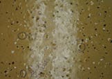
The field phase of this concrete floor coatings forensics case history included five steps: project familiarization and interview; moisture detection; coating thickness measurements; adhesion testing; and microscopic examination, sample collection and photographic documentation.This edition of the F-Files presents the field investigation undertaken to determine the cause of a concrete floor coating failure (Fig. 1). The laboratory forensic work associated with the project, and the conclusions regarding the cause of the problem, will be addressed in a subsequent installment.
Step 1: Concrete Floor Coatings Project Familiarization and Site Interview
Familiarization with the project began with an initial telephone call and an interview with the maintenance supervisor of the building in order to obtain background information on the failure. The following was revealed.
- The existing coating on the floor of a laboratory was cleaned and overcoated. The laboratory contained a variety of equipment, but with exception of cleaning materials, it was essentially a dry operation. The laboratory itself had two interior doors and one double door, but no windows.
- The failure involved blistering of the overcoat system, believed to be within the clear urethane finish coat. The blisters were present along the back corner of the laboratory and near the exterior door.
- The cleaning and painting work was performed by the building maintenance staff. The laboratory was taken out of service during the work.
- There was no specification, just the manufacturer’s product data sheets.
- The work was done in August. Outside doors were opened and floor fans were used for ventilation during application (blowing out) and drying (blowing in). Some days during application were rainy.
- The type of existing floor coating was unknown, but the overcoat system consisted of four coats (two coats of epoxy and two coats of clear moisture-cured urethane).
- The existing floor was cleaned by sanding and detergent washing/rinsing.
- The first epoxy coat was thinned.
- Decorative color chips were broadcast onto the wet surface of the second epoxy coat followed by application of the clear coats.
- All coatings were applied by roller.
- No inspections were performed (i.e., no moisture testing, monitoring of ambient conditions or wet film thickness testing).
- Wet samples of the overcoat products (unopened containers) were available.
- Destructive testing/sampling was permitted.
- The coating manufacturer had been consulted by phone, and based on the information presented by the maintenance supervisor, suggested that blister formation resulted from applying the first clear urethane over the epoxy before adequate curing had been achieved. No reports were prepared.
All of the background information collected must be kept in mind when performing field tests and inspections. Before doing a detailed analysis, do a quick walk-through of the project to understand the “big picture” first, and to identify any obvious failure patterns or trends. This helps to identify specific areas for an in-depth, hands-on assessment.
Step 2: Field Moisture Detection
When examining floor coating problems, it is helpful to determine if there is a correlation between the moisture content within the concrete and the location or locations of the problems. This is especially important for on-grade concrete slabs.
Several test instruments and test methods were available to determine moisture content. For quick comparative assessments, hand-held moisture meters were preferred because they provide instantaneous results. During the field investigation, moisture meters that operate using electrical impedance (as per ASTM F2659), electrical resistance and radio frequency principles were used (Fig. 2).
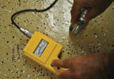
All tests with the moisture meters indicated that the floor was dry in both failing and non-failing areas.Other moisture test methods include the plastic sheet test (ASTM D4263), calcium chloride vapor emission testing (ASTM F1869) and relative humidity (RH) probes that are inserted into the concrete (ASTM F2170). The plastic sheet requires at least 16 hours, and calcium chloride and RH probes require up to 72 hours to complete so they were not used in this case. It should be noted, however, that some manufacturers of the RH probes indicate that results within 3 percent of the RH obtained after waiting 72 hours can be obtained within one hour.
Step 3: Field Coating Thickness Measurements
When examining coating problems on concrete floors, coating thickness measurements are performed to determine if there is a correlation between thickness and coating failure.
Total coating system thickness on concrete floors can be measured nondestructively using an ultrasound coating thickness gage in accordance with ASTM D6132. This can be useful for the measurement of total coating thickness, but for field forensic work, determining the thickness and consistency of the individual layers (including the presence of pinholes and voids) can provide valuable information. Individual coating thickness is typically performed using a Tooke Gage as per ASTM D4138 and/or from cross-sections of field samples that are measured microscopically in the laboratory. Both methods are destructive and field coating repairs are necessary. Sample removal techniques are discussed in the upcoming section on microscopic examination, sample collection and photographic documentation.

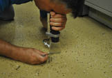
For this failure, the Tooke Gage was used to measure floor coating thickness in both failing and non-failing areas to determine if there was a correlation between thickness and performance (Fig. 3).
The results showed that the thicknesses generally complied with the coating manufacturer’s requirements, and more importantly, that there was no difference in thickness between failing and non-failing areas.
Step 4: Field Adhesion Testing
Visual observations alone are often not adequate to determine the extent of potential problems. A coating can appear to be intact and free of blisters, but possess a level of adhesion that will not withstand the abuse and wear that is expected. Adhesion test results are used by professionals when rendering an opinion as to whether a coating should be repaired or replaced. If a coating is repaired, adhesion tests are also used to confirm that the repair material exhibits an adequate bond to the existing coating.
There are three primary ways to test the adhesion of a coating system. All three methods are described in ASTM standards.
ASTM D3359 involves cutting an “X” or cross-hatch pattern into the coating down to the substrate, applying a pressure-sensitive tape to the test area and removing it. The amount of coating removed is rated according to an ASTM rating scale from 0 to 5, with 5 representing no coating removal.
ASTM D6677 involves cutting an “X” through the coating and probing at the cross-section. The ease of removal is rated subjectively on a 0-to-10 scale with 10 representing no coating removal.
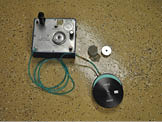
ASTM D7234 involves attaching (using a liquid adhesive) a 2-square-inch surface area loading fixture to the coating surface and removing the fixture with a pneumatic or hydraulic adhesion tester after the adhesive has cured. The tester measures the pull-off force (in psi or kilopascals) needed to detach the test fixture from the coating or substrate.
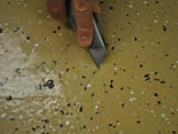
These tests are based on two different testing mechanisms and evaluate two different adhesion properties. The tape and knife adhesion tests are used to evaluate the “shear” or “peel” strength of a coating, while the pull-off test is used to evaluate a coating’s tensile strength, or its resistance to a perpendicular pull. Pull-off testing was the primary means of adhesion testing used for this project (Fig. 4), but supplemental testing was also done using the knife test (Fig. 5).
When documenting pull-off adhesion test results, record the pull-off value and the location of the break. An adhesive break is a clean split between coating layers or down to the concrete surface. A cohesive break is a split within a single coating layer or within the concrete substrate itself. Adhesive or cohesive failures of the glue used to affix the loading fixture to the coating may necessitate that additional tests are performed.
Note that while concrete has tremendous compressive strength, it often does not possess good tensile strength, so the location of the adhesion test break is oftentimes within the concrete itself. When this occurs, little information about the adhesive or cohesive properties of the coating system is revealed, other than the fact that the coating adhesive/cohesive strength exceeds the tensile strength of the concrete substrate.
For the work on this project, the pull-off adhesion in a typical non-failing area measured 525 psi with the break as follows: 15 percent glue, 20 percent cohesive in the concrete and 65 percent cohesive within the red primer coat of the original coating system. These results indicate that the new system adhered well to itself and to the original floor coating. Failing areas were not tested because there was obvious visual blistering and peeling on the coating surface.
Knife testing in failing areas produced poor results with the clear outer urethane layers detaching in large chips (¼-inch and larger) immediately upon insertion of the knife blade. Continued probing of the underlying layers revealed that those layers (both the new beige and original layers) were sound, intact and adherent. Knife tests in non-failing areas showed all coats to be very difficult to remove. The adhesion was excellent.
Step 5: Field Microscopic Examination, Sample Collection and Photographic Documentation
Field Microscopic Examination When examining coating problems on concrete floors, one of the key tests often performed in the field is a microscopic examination. A low-power microscope with 20X-to-50X magnification can be used to identify flaws or deficiencies that would otherwise go undetected. A microscope with a large field of view is also a plus, especially one that has an opening in its base to allow for a knife to be used to probe the surface while viewing under magnification (Fig. 6).
Microscopic analysis also helps to focus the direction of the investigation by identifying the types of field samples that should be collected for subsequent laboratory analysis. For example, the microscope might show the presence of a contaminant between coats or that separation is occurring at different planes within the coating system, thereby influencing the type and number of samples that should be collected.
In this case, the microscopic analysis revealed that the separation was occurring between the beige epoxy layer and the first clear urethane layer, with a slight beige discoloration visible on the underside of the disbonded clear coats. Contamination between coats was not visible.
Sample Collection and Photographic Documentation
The removal of samples must be done methodically and with planning, with consideration of the following.
1. Failing samples — The samples must be representative of the problems observed. Oftentimes, the failure is not the same across the entire surface. For example, the failure of a coating system to the substrate must be treated differently than a failure between coats. In the end, the cause may be the same, but when conducting field analysis and sampling, they must be treated as two separate problems. If more than one type of failure is occurring, representative samples of each type must be collected. &nsbp;
2. Non-failing samples — Non-failing samples are as important as failing samples so that comparisons can be made. Again, they should be representative of non-failing areas, such as both thin and heavy areas.
3. The integrity of a sample must be maintained. For example, peeling/lifted paint on the surface can be contaminated from environmental exposure and should not be used if possible. Collect samples adjacent to failing areas where the poorly adhered paint is still weakly attached to the surface, so that the interface has not been exposed.
4. When possible, sample the failing coating and the underlying remaining coating, material or substrate. Oftentimes, key evidence is on the surface of the coating that remains attached to the substrate, or on the substrate itself.
5. Samples should include the complete coating system and substrate whenever possible. This allows for the sample to be separated in the laboratory so that the interface between layers can be examined. These types of samples can be obtained by cutting a core sample with a concrete core saw (dry) or by chipping the concrete (i.e. using a sharpened masonry chisel).
6. Immediately place each sample in a sealable plastic (polyethylene) bag or in a septum-capped vial and clearly label the sample. Septum-capped vials are particularly useful for preserving coating samples that may be suspected to contain retained solvent. In the absence of septum vials, double- or triple-bagging of samples can also be effective.
7. Prepare a chain of custody for samples for traceability purposes. The form should document information such as the type and location of the sample, laboratory analytical testing required and signature sections acknowledging the person who obtained, transferred or received the samples.
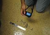
8. Photographic documentation throughout the evaluation process is of vital importance. Photographs of typical failing versus non-failing areas show the type and extent of the defects (for example, concentrated versus randomly scattered and general locations). Handwritten notations on the surface being photographed can enhance the value of the picture and aid in recall when preparing the report. A ruler or some other reference to size is also helpful as shown in Figure 7.
Sample locations should be known. The source and exposure (contamination) of detached coating chips lying on the ground are not known and should not be used.
Conclusion
In summary, the field investigation revealed that the floor was dry in both failing and non-failing areas. The field measurements of the coating showed that the thicknesses generally complied with the coating manufacturer’s requirements, and more importantly, that there was no difference in thickness between failing and non-failing areas. For the work on this project, the pull-off adhesion evaluation in the intact areas showed that the new system adhered well to itself and to the original floor coating. The knife adhesion evaluation revealed that failing areas of coating were predominately the result of detachment of the clear outer layers, and that the underlying layers were sound, intact and adherent. Conversely, the knife adhesion tests in non-failing areas revealed that the adhesion was excellent. The field microscopic analysis of failing areas revealed that the separation was occurring between the beige (epoxy) layer and the first clear (urethane) layer, with a slight beige discoloration visible on the underside of the disbonded clear coats. Contamination between coats was not visible.
The documented field data, notes and observations were combined with the laboratory sample analysis to determine the cause of the coating failure. The laboratory forensic investigation and the conclusions regarding the cause are the focus of Part 2 of this series.
As seen in JPCL
Authors: James D. Machen & Richard A. Burgess
KTA-Tator, Inc. PCS, KTA Tator, Inc., Series Editor
Read part 2 here…
https://ktauniversity.com/concrete-floor-coatings-forensics-case-history-part-2/