While water is life-sustaining to humans, it is detrimental to buildings; especially ones made from single-wythe concrete masonry walls. It causes paint to fail, cracks to form in mortar joints, and blocks to spall. These deficiencies are unsightly and reflect poorly on brand, and over time, moisture intrusion can result in the complete deterioration and failure of the wall. There are multiple ways that water can enter a wall, but the primary focus of this article is the association between air leakage and moisture.
Air leakage in the building envelope increases the cost of heating and cooling by allowing conditioned air to escape to the outside, and unconditioned exterior air to infiltrate the interior. Moreover, many details that allow the passage of air, can also allow the passage of water, or moisture in the air at points of ingress and egress can condense to form liquid water. Once present in a wall, water can essentially defy gravity, moving vertically through capillary action. When water in the wall freezes and thaws, miniscule crevices widen, eventually becoming cracks and spalls. As time goes on, the condition worsens to the point that if no action is taken, entire walls could require demolition because they are no longer structurally sound. Air leakage and water intrusion should be controlled to the absolute minimum that is feasible.
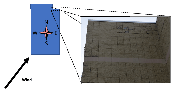
A contributing factor to air leakage is wind hitting a building. The walls that are in the wind’s path are pelted by wind-driven rain, forcing moisture into gaps or openings, such as between the wall and roof. A lesser, but still very real problem occurs in the walls on the opposite side of the building that are exposed to the wind. In this case, the culprit is negative pressure. Negative pressure is created on the outside of a building on the opposite side of the wind, pulling interior air through the wall at deficiencies. In the winter, the interior air is typically warmer and moister than the outside air. If wind comes from the Southwest, and there is a bump-out on the opposite side (Northwest), negative pressure will form in this inside corner, potentially pulling the warm, moist interior air out through openings or other air leakage sites. Freezing can lead to deterioration and spalling of mortar and block. See Figure 1 for an example.
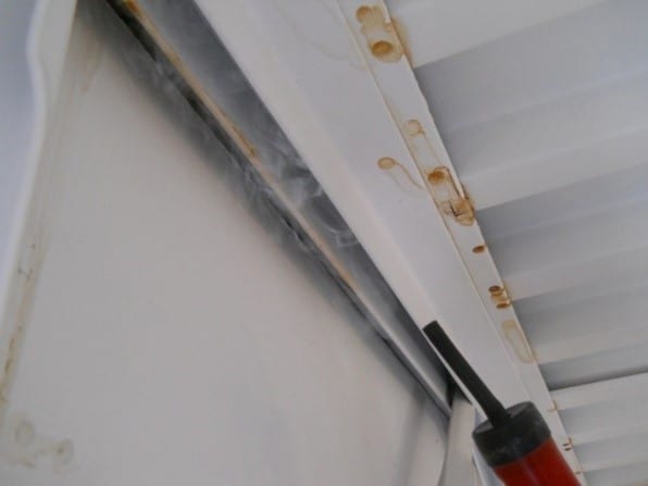
A number of methods are used to determine if air leakage is occurring. Seven methods are described in ASTM E1186, Standard Practices for Air Leakage Site Detection in Building Envelopes and Air Barrier Systems. One of the methods involves the use of a smoke tracer (Smoke Tracer or Theatrical Fog in Conjunction with Building Pressurization or Depressurization). Smoke tracers are typically used in the interior because there is less air movement inside the building than on the outside. If the smoke moves away from the wall, there is air movement into the building. If the smoke disappears into the wall, air leakage is from the inside out. If the smoke hangs in place, the test area is free of leakage. The test is often used at roof/wall junctions and around penetrations in the wall such as gaps around girder supports, as these are major air leakage points (Figure 2).

Localized air leakage sites can be detected by another method described in ASTM E1186 (Chamber Depressurization in Conjunction with Leak Detection Liquid). In this case a leak detection fluid (soap-like fluid) is applied to the surface and a dome placed over the test area. A pressure differential is created inside the dome. Bubbles in the fluid indicate air leakage. This method can be used to detect air leakage in coatings applied to block, at penetrations during construction (such as brick ties), and at roof seams and other junctions (Figure 3).
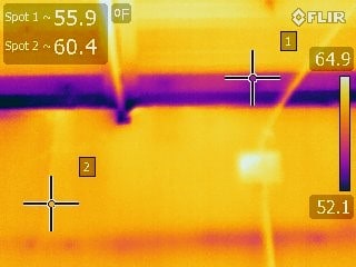
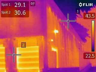
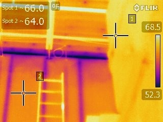
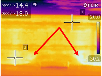
In the winter, interior heat more readily escapes to the outside through gaps in a wall than through the wall itself, with the direction reversing in the summer. In both cases, temperatures at leakage sites will be different than the surrounding temperatures. Infrared cameras can be used to measure temperature differentials to identify air leakage. Darker colors in thermal images represent colder areas; lighter colors represent warmer ones (Figure 4). In a simple wall assembly involving single-wythe concrete masonry block, areas of block, grout, or insulation that are damp retain heat longer than corresponding areas that are dry. Late at night, moisture will show up lighter since it retains the heat from the day. Early in the morning as the wall starts to heat up, the water takes longer to heat up and will appear darker (Figure 5). Accordingly, experience and expertise are required when determining the best time to take infrared images, and in interpreting the results.
Another method for monitoring temperature differentials involves the use of surface and air temperature thermometers and data loggers to measure and log the temperatures at suspected leakage sites. Calculations involving temperature differentials can be performed to determine when vapor in the air will condense and become liquid moisture. However, these equations are dynamic, not static, so results based on given temperatures will not be valid as soon as the temperature fluctuates. Furthermore, heat transfer occurs by different means, including conduction, convection, and radiation, varying wind velocities, the presence of moisture, climate, relative humidity, surrounding reflective substrates, and numerous other properties that cannot be calculated from a single formula. Running multiple computations quickly is best left to a computer, especially when analyzing data over years of time. A software program, WUFI-Oak Ridge National Laboratory (ORNL)/Fraunhofer Institute for Building Physics (IBP), or WUFI-ORNL/IBP has been developed to assist with such an analysis, and help determine where moisture issues within a given wall assembly might occur. Models can be simulated during the design of a building so that changes can be made to keep problems from occurring. The simulations are also useful during forensic analysis to determine the cause of moisture-related failures and to evaluate potential solutions, such as the addition of insulation, or installing coatings of different permeance.
Moisture meters are the most common method used to determine the localized presence of moisture. Some moisture meters assess the conductivity (or resistivity) between the tips of two insulated pins that are pressed against the surface. The conductivity (resistivity) is converted to values indicating the relative moisture content of the surface. Holes to accommodate the probes can be drilled into the surface to determine the relative moisture content at different depths. To obtain a moisture reading below the surface without having to drill holes, moisture meters based on radio frequency or electrical impedance can be used. The radio frequency meter can “read through” coatings and roof membranes to the underlying CMU block or approximately ¾” within the CMU block itself. Figure 6 shows the presence of visible moisture behind the roof membrane where the radio frequency meter displayed a high moisture reading over top of the membrane. The radio frequency meter is especially useful when nondestructive tests are required.
For remedial action, a common air leakage problem occurs at the junction between the roof and the wall. A thorough inspection should be completed to compare the installation against detail drawings. If an air barrier is present, verify that it is continuous and free of breaches or discontinuities. If an air barrier is not present, it might be possible to install one (e.g., rigid and/or spray foam insulation), but the potential benefit needs to be evaluated against the cost.

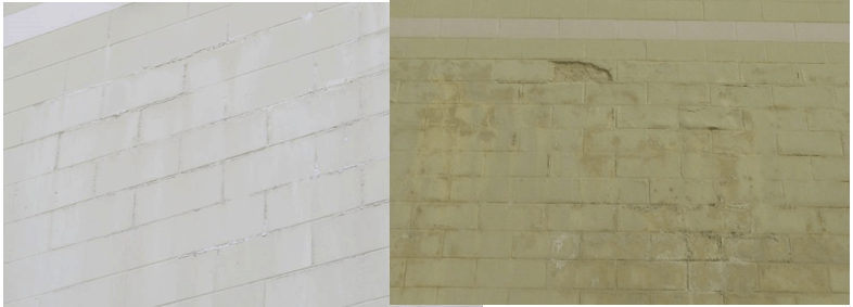
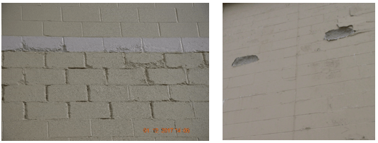
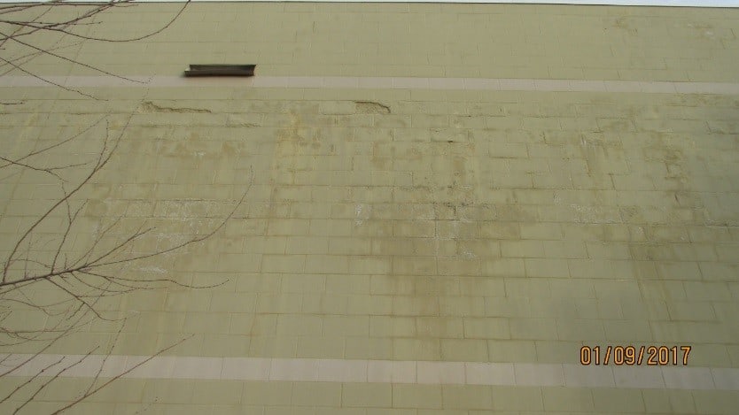
A case study helps to illustrate the use of the various techniques described above. A single-wythe CMU building in Nebraska was experiencing widespread paint failures, significant cracking of walls, deteriorated mortar joints, spalling block, and efflorescence (Figure 7 shows the condition in 2017). Photos of the building were originally taken in 2011, but no remedial work was performed. A comparison of the same wall between 2011 and 2017 is shown in Figure 8. By comparing the photos, it is obvious that the conditions worsened. A common factor present throughout the building was that the moisture failures started near the roofline and carried downward in the wall, lessening closer to the ground. Moisture meters and the infrared camera were used to prove moisture was present and was responsible for the problems, and the roofline was closely investigated, with smoke tests performed and temperature differentials studied. It was concluded that the failures on the west side of the building were occurring at the roof line and along the roof girders where no air barrier had been installed. Figures 9-11 illustrate the exterior wall condition, interior infrared photos showing air leakage, and roof infrared photos showing heat escaping at the roof/wall junction and girder. The inside corner on the northeast corner of the building also had failures near the roof line, but no roof girder was present. It was determined that the failure here was due to a discontinuous air barrier and from pressure differentials when the wind blew from the southwest.
In conclusion, moisture will find its way into holes, or vapor in air can condense into liquid moisture at locations where air can travel through walls, no matter how miniscule the opening. Locations of air leakage can cause a multitude of problems, starting with paint failures and continuing with deteriorated mortar joints and spalling block. Various methods exist to identify the location and cause of air leakage and moisture problems, as well as to solve the issues to prevent further deterioration, and lost energy dollars.