Introduction
According to ASTM staff responsible for maintaining standards developed by Committee D01, “Paint and Related Coatings, Materials and Applications,” ASTM D3359, “Standard Test Methods for Rating Adhesion by Tape Test” is one of the most frequently downloaded standards from Volume 06.01. First published in 1974, it is widely used in a variety of industries and applications. It can be performed in the laboratory, shop, or field on both newly applied and aged protective coating systems. It is relatively easy to perform and does not require specialized equipment. Yet there are many potential issues and challenges with successfully performing such a basic test. This article includes an overview of the testing procedures and presents some common pitfalls associated with performing these tests.
Test Description
The Test Description information in the following section was extracted from an article written by Raymond Tombaugh, Sr. Coatings Consultant with KTA that was posted to KTA University in 2018 titled, “Coating Adhesion Testing using Knife/Tape Methods.”
“Two test methods are described in ASTM D3359: Method A (X-cut), and Method B (Cross-cut). Test Method A is primarily intended for use on coatings/coating systems over 5 mils (125 µm), while Method B is generally used on coatings/coatings systems less than 5 mils thick. Either method can be performed in the shop, field or laboratory. The test was developed for assessing the adhesion of coating to steel but can be used on other hard substrates. The test has also been used successfully on softer substrates (e.g., wood and plaster).
Both tests are performed by scribing the coating to the substrate with a sharp knife blade in a specific pattern, applying a pressure sensitive tape and then rapidly pulling the tape from the surface. When the coating is greater than 5-mils thick, an X-cut (with each leg approximately 1.5-inches long) is made into the film. When the coating is less than 5-mils thick, a cross-cut lattice pattern is created with either six or eleven cuts in each direction. For coatings up to 2 mils thick, eleven incisions are made that are spaced 1 mm apart. For coatings between 2 mils and 5 mils thick, six incisions are spaced 2 mm apart. For both methods, a steel or other hard metal straightedge or template is recommended to ensure straight cuts and, in the case of the X-cut, the correct angle at the intersection (30-45°).
Once the incisions are made, a pressure sensitive tape (with adhesive properties conforming to the requirements of the standard; Figure 1) is applied over the incisions and pressed in place using a pencil eraser. Following a brief “recovery” period of about 60 seconds the tape is removed by grasping the free end of the tape and pulling it off rapidly (not jerked) back upon itself at as close to an angle of 180° as possible. After removal of the tape, the amount of coating removed from the substrate or underlying coating is rated. It is important to evaluate the coated surface and not the back of the tape, since coating debris from the incisions is often removed by the tape.

Adhesion is rated based on the scale provided in the ASTM standard. The scale ranges from 0 “Removal beyond the area of the incisions” to 5 “No peeling or removal.” When Method A is used an “A” is included after the numerical adhesion value (e.g., 3A). Similarly, a “B” is added after the numerical value when Method B is used (e.g., 3B). Table 1 provides the evaluation criteria for Method A; Table 2 provides the evaluation criteria for Method B. The standard also contains a pictorial guide to aid in the rating of the cross-cut (Method B).
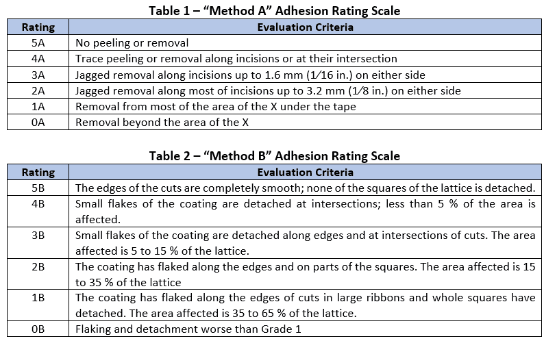
When appropriate, the nature and location of the separation is documented. A cohesive separation is one that occurs within a coating layer; an adhesive separation is one that occurs between coating layers or between the coating and the substrate. Generally, adhesion ratings of 4 and 5 are considered good, adhesion values of 2 and 3 are considered marginal and adhesion values of 0 and 1 are considered poor.
Issues and Challenges
Following are ten issues and challenges when performing tape adhesion testing on coating systems. The list is not exhaustive but addresses some of the more common pitfalls to avoid. Those listed below are in the order in which they would be performed during actual testing.
Using the Appropriate Method: ASTM D3359 describes two test methods for evaluating tape adhesion of a coating system: Method A (X-cut Tape Test) and Method B (Cross-cut Tape Test). The method selected is based on the total thickness of the coating system to be evaluated. Method B is used for coating systems up to 5 mils thick and Method A is used for coating systems in excess of 5 mils. The spacing between incisions for Method B is generally 1mm to 2mm apart depending on the thickness of the coating.
Creating the Correct Angle at the Intersection for Method A: According to the standard, each of the two legs of the X-cut should be 1.5” long and the intersection of the X-cut should produce an angle between 30° and 45°. When this angle is produced correctly, the horizontal distance between the top two legs of the X-cut should be 1”. Since the tape used is 1” wide, the entire X-cut should be covered by the tape. An X-cut intersection that is too wide or too narrow may affect the adhesion rating. A special template (Figure 2) is available to help ensure the X-cut is made correctly.

Creating the Correct Spacing Between Parallel Incisions for Method B: According to the standard, the spacing between parallel incisions is 1mm for coatings up to 2 mils thick and 2mm for coatings greater than 2 mils thick up to 5 mils thick. Incisions made too close together, too far apart, or that do not remain parallel can produce misleading ratings. Incisions made too close together can cause the coating to “ribbon-off” and those made too far apart can result in false high adhesion ratings. A special template (Figure 3) is available to help ensure the spacing is correct. Alternatively, a multi-blade cutter can be used to generate the cross-cut pattern (Figure 4).


Blade Sharpness: Section 5.1 of the Standard (applying to Test Method A) describes the cutting tool as a sharp razor blade, scalpel, knife, or other cutting device and notes the importance that the cutting edge be in good condition. Section 10.1 of the Standard (applying to Test Method B) describes the cutting tool as a sharp razor blade, scalpel, knife, or other cutting device having a cutting-edge angle between 15 and 30° that will make either a single cut or several cuts at once. It also notes the importance that the cutting edge or edges be in good condition. It is common to use a utility knife to make the incisions. A dull blade or cutting edge can cause chipping (or “chatter”), or tearing of the coating along the incision, resulting in a false, low rating; therefore, it is critical that the cutting edge be sharp. Since use of a knife blade in this manner (making an incision down to the base metal or other hard substrate) tends to dull the blade quickly, it may be necessary to replace the blade frequently.
Depth of Incisions: The incisions made with the cutting tool (for Method A or B) must penetrate through all coating layers to the metal substrate using one steady motion. This should be verified visually and with the aid of a magnifier if necessary. This is particularly important when using the multi-blade cutter. All of the blades must remain in contact with, and held perpendicular to, the surface during use, and care taken to assure that all blades cut through the coating to the substrate in a single pull If the substrate hasn’t been reached, the operator needs to move to a new location. It is important not to attempt to re-cut a previous incision as it may result in a false rating.
Removing Chalk/Dirt from the Surface Prior to Test: Since adhesive tape is used in the test, it is important that the adhesive adhere well to the coating surface. Any chalking from deteriorated paint, dirt, oils, moisture, or other surface contaminants will interfere with the adhesion of the tape and could yield false adhesion ratings. It is permissible to clean the surface prior to testing if these surface conditions are present. Also, after the incisions are made, any debris should be removed with a soft bristle brush prior to attaching the adhesive tape.
Tape Type/Using Fresh Tape: Section 5.3 of the Standard describes the tape as 25-mm (1.0-in.) wide semitransparent pressure sensitive type with an adhesion strength agreed upon by the supplier and the user. It also cautions that there may be variability in adhesion strength of the tape from batch-to-batch and with time. The ASTM standard does not require a specific type or manufacturer of tape to use. Currently two companies (SEMicro and Elcometer) manufacture a tape (CHT and P99, respectively) specifically for this test method that possess the same backing and adhesive strength as the tape referenced by earlier versions of the standard (Permacel 99), which is no longer available. Since there is no specific tape to use, it is important to agree on the type to be used in advance of any testing.
Further, Sections 7.4 and 12.6 instruct the operator to remove two full wraps of tape from the roll and discard prior to each day of testing and before performing testing. The adhesive on the tape closest to the outer side of the role and exposed to air may have degraded due to exposure to sunlight (solar radiation) and/or temperature. This practice helps ensure fresh adhesive is on the tape used to conduct testing. Most of these tapes have a shelf life and should not be used once expired. Shelf life can be determined from the Lot No.
Using an Eraser to Ensure Tape Bond: Sections 7.5 and 12.7 state that an eraser on the end of a pencil should be used to ensure good contact between the tape and test area, and to examine the color under the tape to verify good contact. While the location of the eraser (end of a pencil) is likely moot (a separate eraser can be used), the end of the utility knife, thumb pressure or other means of ensuring positive contact are not as effective and may yield different results. An eraser is pliable and can conform to slight surface irregularities, making it an ideal tool for ensuring good contact between the tape and the test area.
Tape Direction of Pull: Sections 7.6 and 12.8 state that the tape should be removed within 90 +/- 30 seconds of application by seizing the free end and pulling it off rapidly (not jerked) back upon itself at as close to an angle of 180° as possible. It is important to peel back the tape and not pull upwards since the purpose of the tape is to remove poorly adhered coating so that the X-cut or cross-cut area can be correctly evaluated; it is not intended to remove intact coatings.
Evaluating the Test Area, Not the Tape: Sections 7.7 and 12.9 instruct the operator to inspect the X-cut area (Method A) or grid area (Method B) for coating removal, not the tape. Since incisions are made into the coating system, the tape will almost always have coating on it; therefore, it is important to base the rating on the test area only.
Evaluation Criteria: Method B (cross-cut) provides words (Table 2 above) to describe the ratings of the amount of coating that might be removed for each rating. Method A (X-cut) does not have a corresponding figure illustrating the different amounts of detachment; only a description of each rating from 5A to 0A (Table 1 above). Therefore, there can be more subjectivity to evaluating the X-cut even though the description of each rating value is relatively straightforward. In some cases, it may be necessary to report a range (e.g., 3-4A) versus a single rating value.

